
Mounting a Wind Generator Mast
How I built a 20-foot mast for my wind generator


Introduction
When pursuing the use of alternate energy sources, two that are usually available to most people are solar or wind. Unless you are an urbanite with no access to the sky or live somewhere where such things are restricted you can usually find at least a limited use of either wind or sun. In a previous tutorial I showed how to build a two-axis solar array that would track the sun and provide a KW of electrical energy. In this one I will show how to mount a small (1 KW) wind generator using a guy wire stabilized mast.
Parts and Tools
To do the same mount that I did you will need the following parts and tools
Parts:
- 1 KW wind generator with mounting hardware and controller
- 50-foot welding leads
- 2 – 10-foot sections of schedule 80 1-1/2 inch steel pipe.
- 2 smooth merchant connectors for 1-1/2-inch steel pipe
- 1 - 1 foot 1 inch steel nipple
- 2 merchant connectors for 1 inch steel pipe
- 1 mounting adapter for small wind generators
- 1 base plate mount for 1-1/2-inch mast
- 6–80-pound bags of pre-mixed strong cement
- 5-5-foot sections of ½ inch rebar
- 4-2-foot sections of 1x6 inch (6 inch true size) boards
- 4 ½ inch by 6-inch steel concrete anchors with nuts and washers
- 2-1/2 by 4-inch bolts with nuts and washers
- Rebar or fence wire
Tools needed:
- Pipe Vise for 1-1/2-inch pipe
- Pipe threader for 1-1/2-inch pipe
- Large drill
- ½ inch high-speed carbide drill bit
- Pipe wrench for 1-1/2-inch pipe
- Metal grade epoxy
- Metal working furnace or acetylene torch
- Metal saw or some means to cut rebar
- Mounted workbench or post vise
- Large level
- Rubber mallet
- Shovel
- Wheel barrow
- Post hole digger and/ or tractor with 8-inch diameter auger
- Hoe
Preparing the Mast
One thing to remember, when you are buying pipe, the size refers to the inside diameter not the outside diameter. For example, 1-1/2-inch pipe is 1-1/2 inch inside diameter and just a shade off of 2 inches outer diameter. You always order fittings, adapters and other items based on inside diameter. If you can get one 20 foot section of 1-1/2 inch pipe do so, it will save you lots of work. However, it was costly to get it delivered to my site so I had them cut it into 2 – 10 foot sections I could fit into my truck easily. Of course, to get the full 20 foot height I wanted, I then had to join the two sections back into a single 20 foot piece.
Also, if you do have it cut, see if they can thread the ends for you. My welding supply couldn’t do it and local gas and plumbing folks only worked with 1 inch pipes so I used Ebay and FaceBook Merchant to find a pipe vise and a threading tool for less than $70 total. I also bought a machine bench from Harbor Freight on which to mount the pipe vise.
The connectors used to join two lengths of pipe in a straight line are called merchant connectors. If your local hardware or plumbing supply doesn’t have them look at Granger.

Figure 1: A merchant connector, they can also be smooth.
The wind generator will come with a mounting flange on the bottom and provide a mounting plate for you to weld on to the mast to mate with it. I found an adapter that allows you to mount the generator mounting flange to the mast without welding a plate on, it was from Cutting Edge Power, but beware, there may be a several week lead time. It may be easier to take the mounting plate and a high strength merchant connector and have them welded together.
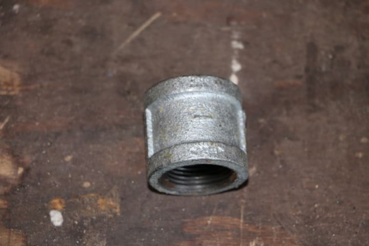
Figure 2: The Adapter Provided by Cutting Edge Power
One of the reasons I mention the specification of piping diameter was because when I ordered the adapter, I assumed it would be sized for the outer diameter of the pipe it fit over so I asked for a 2-inch diameter adapter. Well, they sent me one sized for a 2 inch inner diameter pipe which means the inner diameter of the adapter is about 2-1/2 inches…I’ll show my fix for that later.
Procedures:
Joining the mast sections:
Assuming you have two 10-foot sections of 1-1/2 inch pipe, you will need to join them.
1. To join the pipes using a merchant connector, the ends of the pipes will need to be threaded. To thread the pipe ends:
a. Mount the end of the pipe to be threaded so that a foot or so sticks out of the vise
b. Support the other end of the pipe, I found it easier to thread if you also tied it down. I used a ratchet strap and my deck railing.

Figure 3: Mounting the pipe
2. Once the pipe is firmly mounted so it can't move or rotate, make sure the threader is set to 1-1/2 inch pipe and, using oil, read the pipe for about 2 to 3 inches in length. Be careful the threading cuts are sharp and can easily penetrate the soles of shoes, feet and hands. The threader is a large ratchet it is much easier to use your weight to push it down and ratchet than any other combination.
3. Repeat step two for the second pipe
4. Flip the second pipe around and repeat step 2 on the other end.
5. You should end up with two pipes, one with one end threaded, the other with both ends threaded.
The joint Stiffener
Merchant couplers are not designed to provide sideways strength, merely to fasted pipes together and allow for a water or gas tight seal. I am not worried about the sheer forces when the mast is standing straight up supported by guy wires, but in the process of standing the mast up I would hate for it to bend or break at the merchant connector. Thus, the need for a joint stiffener.
There are several ways to stiffen the joint, welding the connector, welding rebar or other stiffeners to the outside of the joint or providing an inner stiffener to the joint itself. I felt the most strength would be gained from an internal stiffener.
First, I hoped that a 1-inch ID pipe would translate into a 1-1/2 inch OD, but instead it translated into a 1.23 inch OD pipe. So, I purchased the merchant connectors for the 1 inch pipe, unfortunately there were no smooth merchant connectors so I had to purchase ones similar to Figure 1 and grind them to fit just inside the 1-1/2 inch diameter mast pipes.
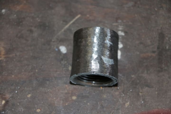
Figure 4: Ground to fit merchant connector.
The connectors where then affixed to the 1 foot long 1 inch pipe nipple and inserted into the 1-1/2-inch pipe.
Before jointing the pipes I threaded the 50 foot welding leads through the two pipe sections and through the joint stiffener. Also coat the exposed 1 inch pipe with a liberal coating of the metal epoxy then slide the pipes together making sure 6 inches of the stiffener is in each side. Once the epoxy cures the joint will be the strongest section of the mast.
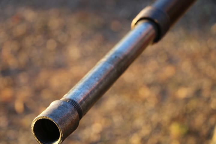
Figure 5: How the stiffener fits in the mast sections
The mast mounting plate.
What inspired my mast mounting plate was the scene in the move Captain America where Steve outsmarts the other recruits by pulling the supporting pin out of the flagpole mount and it pivots on the pivot pin bringing the flag down to the ground allowing him to ride back with the pretty girl in the jeep while the others hike back to base. I searched the net for a similar mount for a large flag pole but only found pale imitations. So, I drew up a quick drawing on Doodle on my iPad and sought out a welder to make one.
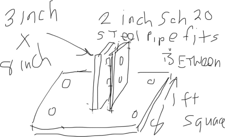
Figure 6: My crude drawing of the mast mount
No doubt soliciting quite a few laughs, I also found someone willing to make it, they provided what you see in Figure 7.

Figure 7: As built Mount
The as built is great, except they put the holes that tie the mount to the platform in such as a way that the anchor ends will interfere with the rotation of the mast. I had them at the corners to not interfere. They also didn’t make sure the pivot pin and securing bolt les lined up between the plates.
So, if your Google foo is better than mine, maybe you can find a pre-made one, if not show a local welder this, or have him watch Captain America.
Mounting pad and Footer
Figure 8 shows my initial mounting concepts. Initially I thought that just a 2x2-6-inch-thick concrete pad would be enough to support the mast, but was later convinced to add a footer under the pad, of course this meant having rebar reinforcement to prevent the base and footer from separating over time.

Figure 8: Initial mounting concept drawing
Figure 9 shows the modified base plus footer. I decided the footer would be three feet deep and 8 inches in diameter, the limits of my tractor PTO auger. I also ditched the PVC liner as it isn’t needed.

Figure 9: Revised pad and footer
Preparing the Mounting Base
1. Using the 4-2-foot 1x6 inch boards, make the concrete form. Make sure the edges are square, I used 2 inch deck screws to fasten the boards together.

Figure 10: Concrete Form
2. Clear the 2 by 2-foot area where the pad will be located and use a shovel and level to level the form on all four sides.

Figure 11: Concrete form leveled.
3. Using the post hole digger or, the auger, bore the footer hole in the center of the pad form. My auger would only do about 2-1/2 feet, so I had to finish out the footer manually with a post hole digger. Make sure the footer hole is as square with the pad as possible.

Figure 12: PTO Auger attachment and augured footer hole
4. If your rebar is new and already cut in 5 foot lengths, great! I had some old stuff laying around, unfortunately someone had bent it into a pretzel, so I cut it into the right lengths and then used my forge to straighten it. Using either a forge or an oxyacetylene torch to heat the rebar to red, carefully bend the rebar so that you have a two inch section that is at right angles to the rest on one end, a three foot straight section and then the remainder bent at the same direction as the two inch section at a 90 degree angle from the straight section.

Figure 13: Properly bent rebar
5. Using the rebar wire or fence wire, wire the rebar together to form the tie between the pad and footer, like Figure 14.

Figure 14: Wired together rebar tie between pad and footer
6. If you haven’t already done so, clear the dirt from boring the footer hole out of the concrete form and make sure it is still level, make sure it has a uniform 6-inch depth.
7. Place the small end of the rebar tie into the hole, add or remove dirt as needed from the footer hole to allow the longer legs of the tie to be at the three-inch level inside the form, they need to be in the center of the lad thickness to be most effective. You may need to trim them to fit just inside the corners of the form.

Figure 15: Placement of the rebar tie
8. Using the wheelbarrow and hoe mix two bags of concrete at a time and fill the footer hole and pad form, use a two foot long, straight board to level the concrete inside the form, there will be a little excess, just scrape it off the side. Be sure the concrete surface is level.
9. Before the concrete sets, insert the concrete anchors through the mounting holes in the mount with the threads up, put on the washers and nuts until, they are three threads from the bottom on all four anchors.
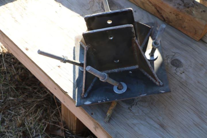
Figure 16: Concrete anchor bolts inserted into mount.
10. At the center of the pad, carefully shove the anchor bolts into wet cement, until the base of the mount is resting on the wet concrete, you may have to use the rubber mallet to set them properly, be sure the anchor ends are pointing away from center. Use the level to be sure the mount is level. The anchor bolt’s nuts should be flush against the surface of the mount base plate when the anchors are properly in place.

Figure 17: Mount installed on pad.
11. Allow the concrete to cure as per manufacturer’s specifications
12. Place the guy wire anchors as shown in Figure 18. I used shed anchors screwed into the ground about 3 feet.

Figure 18: Guy wire Anchor placement
13. For my 20-foot mast with the guy wires attached at 17 feet elevation I ran the anchors out to 17 feet. Note the placement of the anchors in relation to the alignment of the base.
Raising the mast
Once the pad and footer are dry tighten the bolts on the mounting platform, then you are ready to raise the mast.
1. Place the end of the mast section with two drill holes in the mount and insert one of the mounting bolts to act as a axis.

Figure 18: Lower mast section in mount, note I cut one of the anchor ends off to allow it to rotate.
2. Put the merchant connector on the threads on the other end and tighten with a pipe-wrench
3. Insert the joint stiffener into the threaded end of the mast section you just mounted.

Figure19: Merchant connector installed
4. Move the second mast section so the end to be joined to as close as possible to the end of the mast section mounted.
5. Thread the wires for the generator through the section you just moved and then into the lower section, pull through both sections until there is about six inches left at the other end of the second mast section. I used a heavy-duty extension cord with the plugs removed, it provides aa convenient three wire all together cable.
6. Install the cable keeper in the top mast section and knot the wires to keep them from slipping through it. A cable keeper is a small cup or metal piece that is sized to need to be forced into the pipe, it holds the cable, so no weight is on the connection.

7. Mix the epoxy as per manufacturer's instructions and smear a thick coat on the stiffener, then push it halfway into the lower mast section. Slide the upper mast section on making sure half the stiffener is inserted into the top section. I did this by placing a set of vise locking pliers on at the halfway point.
8. Use a pipe wrench to tighten the top mast section into the merchant connector, be sure to tighten to spot torque (Until you see spots.)

Figure 20: Mast sections joined and spot torqued.
9. Allow the epoxy to cure, may take up to 24 hours.
10. Place the guy wire bracket in place and tighten the locking screws. You can do this while the epoxy is curing. Mount it at the 17-foot point on the mast. Align the guy wire attachment points to the positions of the guy wire anchors.

Figure 21: Guy wire collar in place and tightened.
11. Call me insecure but I went ahead and manufactured a brace to fit below the guy wire collar to make sure it stayed in place.

Figure 22: Collar brace to install beneath the guy wire collar
12. If the adapter is on the end of the mast, go ahead and remove it.
13. Mount the adapter to the mounting plate on the wind generator and make sure the leads are pulled through the center hole before you tighten the mounting bolts.

Figure 23: The adapter in place with wires pulled through
14. Take the generator assembly over to the end of the mast. Carefully support the generator assembly while you use solder and then wire nuts to connect the generator output to the cable.

Figure 24: Wiring up the generator
15. Carefully position the connections inside the adapter while you connect the adapter by screwing it back on the end of the mast, tighten with a pipe wrench again to spot torque.
16. Attach the generator blades as per manufacturer's instructions and attach the nose cone.

Figure 25: Attach the blades to the hub, mount and tighten the hub, snap on nose cone
17. At the battery bank, attach the other end of the cable to the inverter and batteries.
18. Prepare 3–26-foot lengths of guy wire.
19. Attach the guy wires to the guy wire collar
20. Using the Pythagorean formula, with a 17-foot right triangle the hypotenuse will be slightly longer than 24 feet. For the guy wire that is going to be parallel to the mast, attach it to the appropriate anchor at 24.5 feet in length, the extra 6 inches will allow the mast to lean slightly forward while you attach and adjust the other two guy wires.
21. Carefully lift the mast until it is resting slightly forward, supported by the attached guy wire. Attach the other two guy wires and adjust their length to 24 feet.
22. Tighten the first guy wire to bring the mast straight, use a level. You may need to adjust the other wires depending how level your lot is.

Figure 26: Mast is raised and straight.
23. Insert the second bolt in the base and spot torque both.
Summary
Well, if you have made it this far I hope you know have a safely mounted wind generator. Of course, the mast could useful for other things as well. Good luck in all your future projects!
A word to the wise - A couple months after I installed this I decided to put on larger blades, so I lowered the mast, that went fine. When I raised the mast I got it vertical, then a wind came up while I was attempting to put in the second bolt. The mast fell, you can't get enough leverge from the foundation end to counter over a hundred pounds of mast and generator if it starts to fall, pinning my leg under the weight of the mast and generator against the concrete pad.

This necessitated an emergency room visit and I was lucky a ladder caught the mast and reduced the pinch angle, or I might be without one leg. Always have a spotter and hook the guy wires before fastening the second foundation bolt.
About the Creator
MICHAEL ROSS AULT
I began writing at age 13. Short stories, novellas, poetry, and essays. I did journals while at sea on submarines. I wrote technical books for a decade before I went back to fiction. I love writing, photography, wood working, blacksmithing
Keep reading
More stories from MICHAEL ROSS AULT and writers in Earth and other communities.
Cenote
The worn stone path leads down through the verdant Yucatan jungle to the edge of the Cenote. How many thousands of years has man come down to the cave, first to sacrifice then in wonder? Long enough to wear the stone, like the steps of some medieval cathedral. Through the undergrowth the birds and other life make their presence known with calls and stirrings. Sweat trickles tickling down my brow as I drop the heavy gear at the water’s edge, the tank, backpack and wing, mask, fins and camera housing. Catching my breath before donning the gear I gaze into the crystalline water seeing the myriad tunnels leading off into the unknown depths of the cave system.
By MICHAEL ROSS AULTabout a year ago in Earth
Revolutionary Climate Action
In the retrospect of my childhood, the memories of the visits to the farm with my parents are a mixture of useful advice and interesting traditions. From my grandpa's idea of planting sweet potatoes underneath rocks to my grandmother's statement that we should plant fruit according to the moon cycles, to my dad's funny invention to control the wind during the rice or cocoa sifting, all these practices were both the usual and the interesting to me. Gradually, I began to think about these habits, it made me to think where they came from and how useful they are. My family usually avoided the cultural traditions which they considered as those which they called the eccentricity of my grandparents. However, my professional career was the climate crisis, where I now, as a consultant, help farmers to set up the resilient agroforests. The road that I have traveled has pushed me to start the Cacua Project, a project that is centered on the creation of the agroforests that are resilient and the collaboration between the farmers to the ecosystems management. Hence, I have combined the old knowledge with the modern research, which has a concrete aspect that deals with the climate change. I have gradually come to the conclusion that the old stories and practices handed down from generation to generation are the most beneficial. The partnering with the farmers, we conducted the experiments that verified some of the traditional methods. In addition, the rocks placed under the crops facilitated the drainage and at the same time it drew the good organisms. The method of planting by moon cycles turned out to be successful in the organization of irrigation and pollination by being in sync with the natural insect activity and the water cycles. Even the wind-whistling technique appeared to influence the air, therefore it was beneficial in the agricultural work. The jewels of wisdom which were taught by the ancestors to us are the ones that gave us the necessary tips for the better way of landscape protection. Ever since I was a young environmentalist, I have been committed to several life choices that elude what I consider good for the planet.
By Wes Wesley5 days ago in Earth
How The Internet is CHANGING Your Brain
With 13% of the world's population using social media, they clearly have a significant effect on society. However, what might be said about our bodies? The following are 5 insane ways that social Your brain is currently being affected by media and the internet! Can't log off? Shockingly, 5-10% of web clients are really incapable to control how much they spend on the internet. Despite the fact that it is a mental addiction rather than a substance addiction, mind sweeps of these individuals really show a comparable impedance of districts that those with drug reliance have. In particular, there is a reasonable corruption of white matter in the locales that control close to home handling, consideration and navigation. Since social media furnishes quick compensations with very little exertion required, your cerebrum start to rewire itself and cause you to crave these stimuli. And you start to want more. of this neurological energy after every association. Sounds like something from a drug, right? We likewise see a shift while taking a gander at performing multiple tasks. You might believe that social media users media or continually switch among work and sites are better at performing multiple tasks, yet studies have discovered that heavy media users perform significantly worse during tests on switching tasks Expanded performing various tasks online diminishes your minds capacity to channel out obstructions, and could in fact make it harder for your mind to commit data to memory. Like when your telephone hums in useful work. Or on the other hand wait...did it even buzz? Ghost Vibration Condition is a somewhat new mental peculiarity where you think you felt your telephone go off, yet it didn't. 89% of test subjects in one study said they at least once every two weeks, experienced this. Apparently, our brains now perceive a tingle as a genuine vibration from our telephone. As insane as it appears, innovation has started to rewire our nervous systems, and our brains are being stimulated in a way they have never been before. been done in the past. Dopamine, a chemical that makes you feel good, is also released when you use social media. Utilizing X-ray filters, Researchers discovered that people's reward centers are significantly more active when they are discussing their own perspectives, rather than paying attention to other people. Not surprising at all - We all enjoy discussing ourselves, right? However, it would seem while 30-40% of eye to eye discussions include conveying our own encounters, around 80% of web-based entertainment correspondence is self included. A similar piece of your mind connected with climaxes, inspiration and love are invigorated by your virtual entertainment use - and, surprisingly, more so when you realize you have a group of people. Our body is physiologically remunerating us for discussing ourselves on the web! However, it's not all so self-centered. In fact, relationships studies have shown that partners will generally like each other more assuming that they meet interestingly online as opposed to with an up close and personal connection. Whether this is on the grounds that individuals are more unknown or maybe all the more clear about their future objectives, there is a factual expansion in effective organizations that first began online. Therefore, even though the internet has altered our verbal communication with increased physical distance, the most important people might end up even closer. Regarding social media, you asked us questions on Facebook, Instagram, and Twitter, tumblr, google+, and every other social media platform we could find, and we produced a Q&A video on Google+. AsapTHOUGHT! So assuming that you feel getting a few insider data on AsapSCIENCE and in the background, Use the link in the description to check it out! Got a consuming inquiry you need responded to? Ask it in the remarks or on Facebook and Twitter. We likewise at long last got a PO Box, for every one of you astounding science darlings who have mentioned to mail us or send us other things over the years. Furthermore, we'd very much want to hear from every one of you! So Use the address displayed on the screen or in the description box as you please. Also, subscribe to receive additional weekly science videos! With virtual entertainment locales being utilized by ⅓ of the whole world, they've obviously had an important factor in society. Be that as it may, shouldn't something be said about our bodies? The following are 5 insane ways that social media and the web are influencing your mind at the present time! Can't log off? Shockingly, 5-10% of web clients are really unfit to control how much they spend on the internet. Despite the fact that it is a mental addiction rather than a substance addiction, In fact, brain scans of these individuals reveal a similar impairment to with drug reliance have. In particular, there is a reasonable debasement of white matter in the parts that control how emotions are processed, how you focus, and how you make decisions. Since social Media gives you immediate pleasure with little effort, so your brain starts to rework itself, making you want these feelings. Also, you start to long for more of this neurological fervor after every connection. Sounds similar to a medication, right? We likewise see a shift while taking a gander at performing various tasks. You could feel that the individuals who utilize social Studies show that people who use media or constantly switch between work and websites are better at multitasking. have found that while contrasting weighty media clients with others, they perform a lot of more regrettable during tests on switching tasks Expanded performing various tasks online lessens your cerebrums capacity to channel out impedances, and could actually make it harder for your mind to commit data to memory. Like when you're working productively and your phone rings. Or wait, was it even done? buzz? Ghost Vibration Condition is a generally new mental peculiarity where you think Your phone should have sounded, but it didn't. 89% of test subjects in one study said they at least once every two weeks, experienced this. Apparently our cerebrums presently see a tingle as a genuine vibration from our telephone. Technology has begun, despite how crazy it may seem. to rework our sensory systems - and our cerebrums are being set off in a manner they won't ever have been done in the past. Dopamine, a chemical that makes you feel good, is also released when you use social media. By way of MRI scans, researcher found that the prize communities in individuals' minds are considerably more dynamic when Instead of listening to other people, they are discussing their own points of view. Not surprising at all - we as a whole love discussing ourselves right? However, it turns out that 30 to 40 percent of face-to-face discussions include imparting our own encounters, around 80% of virtual entertainment correspondence is self-centered. Your brain's regions associated with orgasms, motivation, and love are stimulated by your use of social media, and even more so when you are aware that you have a following. We are receiving a physiological reward from our body for expressing ourselves online! However, it's not all so self included. In fact, relationships studies have shown that partners tend to like one another more when they meet for the first time online as opposed to in person. a face-to-face exchange. Whether this is on the grounds that individuals are more mysterious or maybe all the more clear about their future objectives, there is a measurable expansion in fruitful organizations that began on the web. So while the web has changed our verbal correspondence with increased physical distance, the most important people might end up even closer.
By Ibok Gerardabout 4 hours ago in Earth
Red Shelves
Death is a black hole. Think about it. A black hole is the corpse of a star, something once warm and bright, now come to the end of its life cycle. But some will argue that the cycle of life does not end with death. That death is merely another path we must walk once our bodies expire and our souls ascend. In that moment, when the fuel in the star’s chemical tank hits empty and the shiny matte coat explodes into supernova, the mass left behind – the corpse – becomes a black hole. We understand that, around such a vast cadaver, dimensions work a little differently in death to the way we’re used to in life. For example, light cannot escape the pull of a black hole when it hits the point of no return. That’s where it gets its colour. Space itself is contorted by a black hole. That’s where it gets its funny shape. Even time. Time slows right down the closer you get to it. The closer you get to a black hole. The closer you get to death.
By Matthew Curtis5 days ago in Humans


Comments
There are no comments for this story
Be the first to respond and start the conversation.