
How to Test a Fuel Pump Relay, Wiring, and Ground
A practical essay on diagnosing fuel-pump electrical problems before replacing the pump

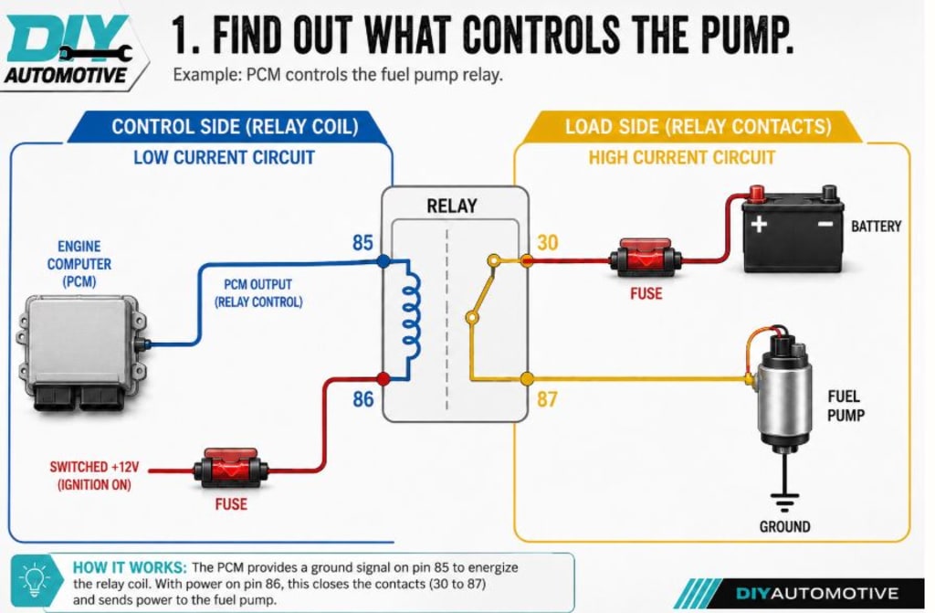
When a fuel pump does not run, operates only when a jumper is installed, or produces low fuel pressure, many people immediately assume that the pump has failed. Although the pump may be defective, it is not always the source of the problem. A weak fuel-pump relay, burned relay socket, damaged wire, poor electrical connection, or corroded ground can prevent a good pump from receiving the voltage and current it needs.
Testing the entire circuit before replacing the pump can save time and money. It can also prevent a new pump from being damaged by the same electrical fault that affected the original one.
Before beginning, obtain the correct wiring diagram and connector information for the vehicle. Fuel-pump circuits vary widely between vehicles. Some use a conventional relay, while others use a fuel-pump control module that adjusts pump speed by changing voltage or a duty-cycle signal. A control module should not be tested or bypassed like a standard relay.
Safety is especially important when working near the fuel system. Keep sparks, cigarettes, open flames, and other ignition sources away from fuel vapors. Use properly fused jumper wires and test probes that fit the connectors without spreading the terminals. Any temporary bypass should be removed as soon as testing is finished.
A fuel-pump relay normally contains two separate circuits. The control side is the low-current circuit that activates the relay coil. One side may receive power while the vehicle computer controls the ground on the other side, although the exact arrangement depends on the vehicle. The load side carries the higher current required by the pump. Battery power usually passes through a fuse, enters the relay, travels across the relay contacts, and then continues to the fuel pump.
Hearing the relay click does not prove that it is working correctly. The sound only shows that the relay’s internal mechanism moved. The contacts may still be burned or unable to carry the pump’s current. A loose, corroded, or overheated relay socket can create the same symptom.
Begin the diagnosis by connecting a scan tool and recording all trouble codes before clearing anything. Look for codes related to fuel-pump control, fuel pressure, low voltage, anti-theft operation, communication problems, and the crankshaft-position signal. If the scan tool displays fuel-pump command data, monitor it while turning the ignition on or cranking the engine. Some scan tools can command the pump on for testing.
The pump command tells you what the vehicle computer is requesting, but it does not prove that the relay, wiring, and pump carried out that request. If the command never turns on, check whether the computer is receiving an engine-speed signal during cranking. A missing crankshaft-position signal can prevent the computer from operating the pump. Also check the anti-theft system, because some vehicles will disable fuel-pump operation when starting authorization is missing.
Next, check the fuse and power feed. Use the wiring diagram to identify every fuse supplying the fuel-pump relay or control module. Test for voltage on both sides of the fuse while the pump is supposed to operate. A fuse can appear visually intact while having a cracked element or a poor connection in the fuse box.
If voltage is present on one side of the fuse but not the other, remove the fuse and inspect both the fuse and its socket. If the fuse is blown, do not repeatedly install new fuses. A shorted wire, damaged pump, failed relay, or excessive current draw may be causing the fuse to open. The underlying problem must be found before the circuit is powered again.
After checking the fuse, identify the relay-control terminals using the connector diagram. With the pump commanded on, verify that the relay coil receives the power and ground it needs. If one side is missing, follow that part of the circuit. Possible causes include a missing ignition feed, a missing computer-controlled ground, damaged wiring, a poor module ground, an anti-theft problem, a missing engine-speed signal, or a communication fault.
Do not assume that the engine computer has failed simply because the relay does not receive a command. The computer may be responding correctly to another problem. Its inputs, powers, grounds, and communication lines should be checked before condemning the module.
Once the relay control circuit has been verified, test the load side. Check for battery power entering the relay and power leaving the relay toward the pump while the relay is energized. If the relay has a proper command and battery feed but no output, inspect the relay and socket carefully.
Look for darkened terminals, melted plastic, corrosion, loose connections, or terminals that no longer grip the relay pins firmly. Swapping the relay with another identical relay can provide a quick comparison, but the replacement must have the same part number and pin arrangement. If swapping the relay restores pump operation, inspect the socket before finishing the repair. A loose socket may cause a replacement relay to overheat and fail again.
The next step is to measure voltage directly at the connected fuel pump. Leave the pump connector assembled and back-probe it with suitable terminal tools. Command the pump on and measure voltage across the pump’s power and ground terminals. Compare this measurement with the battery voltage at the same moment.
If battery voltage remains healthy but voltage at the pump is significantly lower, the circuit is losing voltage somewhere between the battery and the pump. The loss may be occurring at the fuse, relay contacts, relay socket, wiring, connectors, splices, or ground circuit.
If the pump receives the correct voltage but remains silent, check the connector fit, pump current draw, and pump condition. Do not force ordinary meter probes into a connector. Oversized probes can spread the terminals, causing an intermittent problem after the connector is plugged back together.
Voltage-drop testing is one of the most useful ways to find resistance in a fuel-pump circuit. A damaged connection may show full battery voltage when the pump is disconnected but lose voltage when the pump tries to operate. Voltage-drop testing measures the circuit while current is flowing, which reveals restrictions that ordinary voltage checks can miss.
To test the power side, leave the pump connected. Place one meter lead on the battery positive post and the other on the pump’s power terminal. Command the pump on and observe the reading. The meter shows how much voltage is being lost along the power path.
Compare the result with the vehicle manufacturer’s specification. There is no single voltage-drop limit that applies to every fuel-pump circuit. If the loss is excessive, divide the circuit into smaller sections. Test across the fuse, relay contacts, relay socket, connectors, splices, and individual sections of wire. The problem will be located between the last point that tested correctly and the first point that showed excessive voltage loss.
The ground side must be tested in the same way. Place one meter lead on the pump’s ground terminal and the other on the battery negative post. Run the pump and observe the voltage drop. A high reading indicates excessive resistance in the ground path.
Inspect the ground wire, connectors, splices, ground eyelets, crimped connections, and body or frame grounding points. A ground may look clean from the outside while being corroded inside a crimp or underneath the insulation.
A continuity beep does not prove that a fuel-pump ground is good. A continuity test uses very little current, while the pump requires much more current during operation. A connection can pass a continuity test and still fail when the pump is under load.
Current testing provides another way to evaluate the pump and circuit. No current may indicate an open wire, poor connection, or open pump motor. Excessive current may suggest that the pump motor is binding or failing internally. Uneven current can also indicate internal wear.
A current clamp and oscilloscope can display the repeating pattern produced by the pump motor. This can be helpful when diagnosing an intermittent pump, although it is not required for every repair. Current readings should always be considered alongside pump voltage, fuel pressure, fuel level, and the manufacturer’s specifications. There is no single current value that applies to every fuel pump.
A fused jumper can sometimes be used to bypass the relay contacts and send power directly into the pump circuit. This test should only be performed after identifying the correct load terminals from the wiring diagram.
If the pump runs with the bypass, you know that at least part of the downstream circuit can make the pump operate. However, this does not prove that the relay is the only problem. You must still check pump voltage, ground voltage drop, current draw, fuel pressure, and the normal relay-control circuit.
The vehicle computer may not be commanding the relay because it is missing an engine-speed signal, detecting an anti-theft problem, or experiencing a communication fault. Remove the bypass immediately after testing. Leaving it installed may cause the pump to run continuously, drain the battery, or eliminate the vehicle’s normal safety shutdown controls.
The test results should determine the next diagnostic step. If there is no pump command, check cranking RPM, anti-theft data, related trouble codes, and the computer’s powers and grounds. If the command is present but the relay does not switch, check relay-control power, the control ground, the relay, and the socket.
If the relay switches but has no output, inspect the relay’s load feed, contacts, socket, and output wire. If the relay output is good but the voltage at the pump is low, perform voltage-drop tests on the power wire and connectors. If power at the pump is good but the ground shows excessive voltage drop, inspect the ground wire, splice, connector, and grounding point.
If the pump receives correct voltage and ground but does not run, check the connector fit, current draw, and pump itself. If the pump runs but fuel pressure is low, test loaded pump voltage, fuel pressure, restrictions, the pressure regulator, and pump output. If both pump voltage and fuel pressure are correct, return to other causes of a crank-no-start condition, including spark, injector command, RPM data, compression, and timing.
Intermittent faults require testing while the problem is occurring. Keep the meter or scan tool connected and monitor pump command, battery voltage, cranking RPM, pump voltage, ground voltage drop, and fuel pressure. Use the meter’s minimum and maximum function or a graphing feature if available.
Pay attention to which signal disappears first. If the RPM signal drops out before the pump command turns off, the pump circuit may be responding normally to the missing engine-speed signal. If pump command remains active while pump voltage or fuel pressure falls, continue testing the relay, wiring, ground, and pump.
You can gently move the wiring harness while monitoring the readings. Pay special attention to areas near the fuse box, connector bends, body seams, harness clips, and locations where the wiring may rub against metal. Do not pull hard enough to create a new fault.
After completing a repair, repeat the measurement that originally identified the problem. Confirm that the pump receives the correct voltage, power-side and ground-side voltage drops are within specification, and that the connector remains cool and secure. Then perform a fuel-pressure test under the same conditions that caused the original symptom, such as a hot restart, extended cranking period, or heavy-load situation.
If the fuel pump receives proper voltage and ground, and fuel pressure remains within specification, but the engine still will not start, continue with a broader crank-no-start diagnosis. Check spark, injector command, RPM data, compression, and timing.
Testing the relay, wiring, and ground before replacing the fuel pump is an important part of accurate diagnosis. A pump should not be condemned until the circuit has been tested under load. Careful voltage, voltage-drop, current, and fuel-pressure testing can reveal the real problem and prevent an unnecessary replacement.
About the Creator
Mark Lim
Hi I am mark an automotive student and a car, tech and food enthusiast ! Im gonna try and post daily & hope you enjoy what I write and do share my page with people you know. I would gladly appreciate it! Cheers
Enjoyed the story? Support the Creator.
Subscribe for free to receive all their stories in your feed.
Comments
There are no comments for this story
Be the first to respond and start the conversation.