
The Real Reason Your Sheet Metal Part Is Over Budget And How DFM Fixes It
DFM is not a checklist you run at the end. It is the difference between a quote that works and one that doesn't.

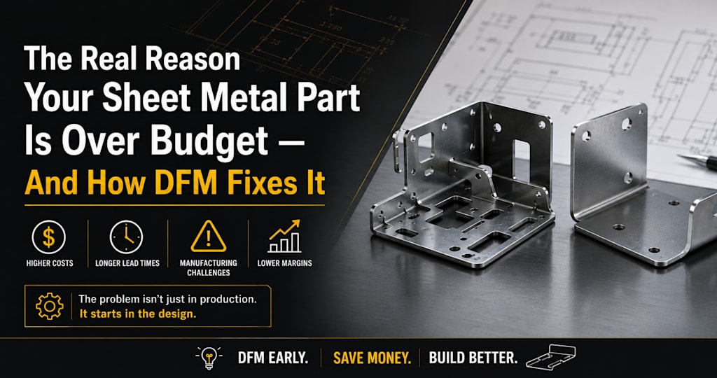
You have a complex sheet metal part. The CAD model looks right. The tolerances are specified. You send it out for fabrication, and the quote comes back far higher than you budgeted for.
Sound familiar? You are not dealing with a pricing problem. You are dealing with a design problem disguised as one.
The cause, in most cases, is a failure to design for manufacturability DFM for short. DFM means making deliberate design decisions that reduce the cost, effort, and risk of fabricating a part, without compromising its function. It is not a checklist you run at the end of a project. It is a discipline you apply from the moment a part concept takes shape.
We provide sheet metal design services to engineering teams across the US, UK, Europe, Canada, and Australia. The industries vary. The core mistakes do not.
When to Apply DFM and Why Earlier Is Always Better
The cost of fixing a design problem scales sharply with how late it is discovered. A DFM issue caught during concept design costs almost nothing to correct. The same issue caught after fabrication has started can cost multiples of the original part price in rework, scrap, and lost time.
• Design stage: Fixing a DFM problem costs almost nothing.
• Pre-production review: Costs time, typically one revision cycle.
• After fabrication begins, costs include real money, scrap, rework, tooling, and delay.
This is especially critical for engineers working on complex enclosures, medical storage units, or industrial equipment panels and parts where the geometry is intricate, the tolerances matter, and the volume may be too low to absorb rework costs easily.
The right time to apply DFM is at the start of the design process. The second-best time is before the drawing leaves your desk.
The Real Reasons Complex Sheet Metal Parts Get Expensive
Fabricators' price is based on difficulty, and difficulty comes from predictable, avoidable design decisions. Here are the four most common cost drivers we see when reviewing client drawings.
1. Tight Tolerances That the Process Cannot Hold Economically
Sheet metal tolerancing is fundamentally different from CNC machining. In machining, ±0.002" is routine. In sheet metal, a single bend typically carries a tolerance of ±0.010" or more, depending on material and tooling", and that stacks with every additional bend in the part. Specifying machining-level tolerances on a formed sheet metal enclosure forces the fabricator into slow, manual operations, and they price accordingly
The result: you pay a significant premium for tolerances that, in most cases, are not functionally necessary.
2. Bend Radii That Force Specialty Tooling
Default bend radius values in SolidWorks and similar CAD packages do not match what most fabricators run on their press brakes. A design that assumes a tight bend radius the shop cannot achieve with standard tooling triggers one of two outcomes: a custom tool order adding weeks of lead time and high cost, or a return to the engineer for redesign, adding delay without adding value.
3. Features That Look Simple in CAD but Are Expensive to Form
Embossments, louvers, complex cutouts near bend lines, and flanges too short to seat properly in a V-die are common examples. Each creates friction in the quoting and production process. Fabricators either add contingency to the quote or flag the design for redesign. Either way, it costs you time and money.
4. Incomplete or Ambiguous Shop Drawings
Missing bend directions, unclear hole callouts, absent finish specifications, and dimensions that conflict between the 3D model and the 2D drawing are among the most common causes of rework and cost escalation. A fabricator who cannot quote confidently from your drawings will either add a buffer to the price or come back with clarification requests, sometimes multiple times, before production can begin.
DFM-First Sheet Metal Design: What It Looks Like in Practice
Each of the four cost drivers above has a corresponding fix. Here is what applying DFM correctly looks like for each one.
Fix 1: Tolerance Only What Is Functionally Critical
Walk through every dimension on the part and ask: what happens if this is off by 0.015"? If the answer is nothing important, the tolerance does not need to be tight. Reserve close tolerances for mating surfaces, mounting holes, and functional interfaces. Everywhere else, give the fabricator room to work efficiently.
This single change tolerancing only what matters is consistently one of the fastest ways to reduce fabrication cost without changing the part in any meaningful way.
Fix 2: Design to the Fabricator's Tooling, Not to CAD Defaults
The best sheet metal designs are built with a specific fabrication process in mind. That means knowing which press brake tooling is available, what the shop's standard bend radius values are, and whether the part will be laser cut or CNC punched. When we handle a complex enclosure project, this dialogue happens before the model is finalised, not after the quote comes back too high.
Aligning bend radii to the fabricator's standard tooling library is a small design change that removes a large cost premium.
Fix 3: Eliminate Features That Add Cost Without Adding Function
Complex features are sometimes necessary. Often, they are not. A structured DFM review will identify louvers, embossments, or cutout geometries that can be simplified or replaced without any loss of function and with a significant reduction in fabrication cost and lead time.
Fix 4: Produce Shop Drawings That Fabricators Can Actually Use
A complete sheet metal shop drawing communicates everything the fabricator needs without a single follow-up question. That means all bend angles and directions are clearly indicated, tolerances are explicitly called out on critical dimensions, finish and material specifications are complete, and hardware callouts are matched to standard fastener libraries.
We produce sheet metal shop drawings to this standard as a core part of every design engagement. The goal is a drawing package that goes straight to production, no clarification loops, no revision cycles, driven by documentation gaps.
What This Looks Like in Practice
A client came to us with a 14-bend sheet metal enclosure for an industrial control unit. The original design had been quoted by two fabricators, both returning prices significantly above budget. The drawings specified machining-level tolerances across all dimensions, a bend radius that required a custom punch, and a louver pattern positioned too close to a bend line.
After a DFM review, we made three changes: tolerances were relaxed on non-critical dimensions, the bend radius was adjusted to match the fabricator's standard tooling, and the louver pattern was repositioned. The part geometry and function did not change. The fabrication cost dropped substantially, and the part went into production within the original timeline.
DFM Checklist: Before Your Sheet Metal Drawing Leaves Your Desk
Apply these checks before any complex sheet metal part goes to fabrication. Each point maps directly to the cost drivers covered above.
• Bend radii: Match them to the fabricator's standard press brake tooling, not the defaults set by your CAD software.
• Tolerances: Apply tight tolerances only to mating surfaces, mounting holes, and functional interfaces. Everywhere else, give the fabricator a working room.
• Flange lengths: Keep every flange at a minimum of 4× material thickness so it seats properly in the V-die.
• Hole placement: Position holes at least one material thickness away from any bend line to prevent distortion during forming.
• Bend callouts: Indicate all bend angles and directions explicitly on the shop drawing; never assume the fabricator will infer them from the model.
• Hardware holes: Size hardware holes to match standard fastener libraries such as PEM. Non-standard sizes add cost and lead time.
• Finish specifications: Confirm that finish callouts are current and achievable by modern fabrication shops. Outdated specs cause delays at the quoting stage.
• Flat pattern accuracy: Verify the flat pattern unfolds correctly in CAD using the K-factor appropriate for the material and tooling, not the software default.
• Drawing consistency: Confirm all dimensions match between the 3D model and the 2D shop drawing. Conflicts between the two are among the most common causes of fabrication errors.
• Feature clearance: Ensure louvers, cutouts, and embossments near bend lines are positioned to avoid tooling interference during forming.
If your drawing passes every check, it is ready to Fabricate
If it does not, those are exactly the points where your quote will come back higher than it should or where the fabricator will come back to you with questions.
Most of these issues take minutes to fix at the design stage. At the fabrication stage, they take days or weeks and cost real money. The checklist above covers the most common ones, but complex parts often have compounding issues that a quick review can surface before they become expensive.
We work with engineering teams across the US, UK, Europe, Canada, and Australia on sheet metal projects that are too complex for a generalist and too important to get wrong. Our sheet metal design services cover everything from initial modelling through to complete shop drawing packages, so your design is production-ready before it ever reaches the fabrication floor.
If you want a set of experienced eyes on your drawings before they go out, send us your CAD file or shop drawings, and we will identify the specific issues likely to drive cost with clear recommendations to fix them.
Send your drawings to: www.teslamechanicaldesigns.com/sheet-metal-design-services.php
About the Creator
Tesla Mechanical Designs
Tesla Mechanical Designs is a global mechanical engineering partner providing machine design, product development, CAD drafting, and CAE analysis to help manufacturers reduce costs and speed up time-to-market.
Enjoyed the story? Support the Creator.
Subscribe for free to receive all their stories in your feed.
Comments
There are no comments for this story
Be the first to respond and start the conversation.