
Selecting Industrial Butterfly Valves for Water Treatment
industrial butterfly valves can be a practical choice for water-treatment lines

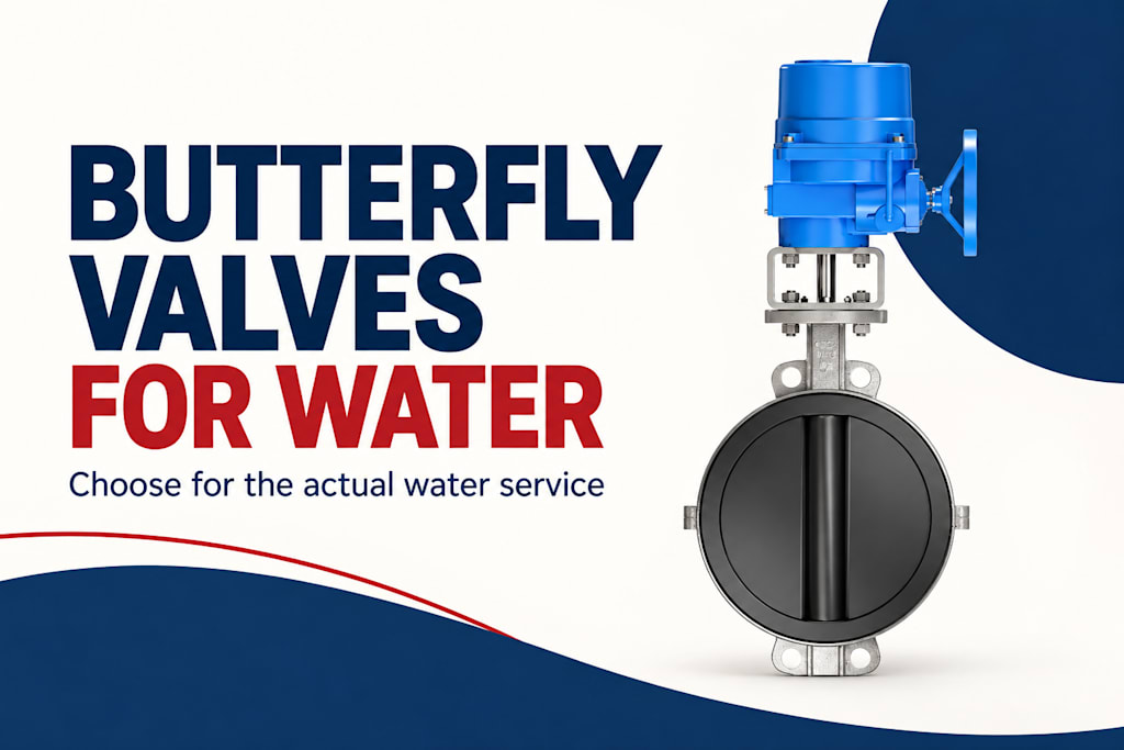
because a rotating disc provides a compact way to isolate or regulate flow. The appropriate construction depends on what the water contains, how much pressure the closed valve must hold, which materials contact the fluid, and how frequently the valve moves. “Water service” alone is not a sufficient specification.
A clean-water outlet, a backwash line, and a chemical-dosing connection have different duties. Even within one treatment plant, temperature, sediment, disinfectants, and cleaning procedures can change the material and operating requirements. Selection becomes more useful when each valve is tied to its location in the process rather than purchased as a generic pipe accessory.
Define the water before choosing the seat
Start with the normal fluid and the conditions it can develop during operation. Identify suspended particles, abrasive grit, chemical concentration, and temperature. Include intermittent exposure during cleaning or disinfection. A valve that sees a different chemical for a short period still needs materials that can tolerate that exposure.
Elastomer seats are commonly considered for many water duties because their compliant sealing surfaces can provide effective shutoff within their ratings. However, “rubber” is not a material specification. EPDM, nitrile, and other compounds differ, and performance also depends on the particular formulation and service conditions.
Compatibility tables are useful for preliminary screening, but they should be interpreted with concentration and temperature in view. A rating for one chemical at one condition does not automatically describe a mixed stream. The disc, shaft, secondary seals, and any coating need attention as well as the main seat.
Match the construction to the hydraulic task
A butterfly valve leaves a disc in the flow path even when open. That differs from a full-bore ball valve, where the open passage can closely resemble the connected pipe. The disc’s presence affects pressure loss and the space needed for movement, although a butterfly arrangement can be attractive where compactness matters.
For isolation, establish the maximum differential pressure across the closed valve and the required leakage performance. For throttling, assess the intended operating positions and the pressure drop at each condition. A valve selected for occasional shutoff should not automatically be assigned to continuous regulation merely because its actuator can stop partway.
The industrial butterfly valves category includes several constructions, including lined and offset designs. The useful comparison is between the specific constructions suitable for the water duty, not between broad claims that one valve type is always best.
Consider flow velocity and pressure changes
High velocity can influence pressure loss, dynamic torque, and wear where particles are present. Closing a valve also changes the movement of water through the piping. The resulting transient depends on the pipeline, pump, valve movement, and other system features. A short travel time is therefore not automatically an advantage.
For an illustrative calculation, assume 50 cubic meters per hour passes through a pipe with an actual internal diameter of 0.10 meter. The flow is about 0.0139 cubic meter per second. Dividing by the circular area, approximately 0.00785 square meter, gives a mean pipe velocity of about 1.77 meters per second.
That is a pipe-flow example, not a butterfly-valve sizing result or a recommended velocity limit. The local velocity around a partly closed disc can be much higher. The example shows why actual bore and operating flow belong in the selection discussion, especially when the valve is expected to throttle.
Plant duty
Selection priority
Detail that is easily missed
Treated-water isolation
Seat compatibility and shutoff
Disinfection exposure
Backwash line
Repeated operation and solids
Changing flow direction
Sludge-related service
Solids behavior and clearances
Particle accumulation
Cooling-water branch
Hydraulic performance
Available differential pressure
Chemical-bearing stream
Complete wetted-material match
Cleaning and concentration changes
Leave physical room for the disc and actuator
The installation envelope includes more than face-to-face length. The disc needs clearance through its full travel, including any portion that projects beyond the valve body. Adjacent pipe bores, reducers, linings, or other equipment can interfere with that movement even when the nominal flange sizes match.
The flange arrangement also matters. Wafer, lug, and double-flanged constructions have different mounting characteristics. Whether a valve can be used at the end of a line or with downstream pipework removed depends on the specific design and rating. Do not infer that capability from the general term “lug valve.”
Allow access for actuator removal, manual operation, and inspection. A valve squeezed between structural members may be easy to draw on a piping diagram and difficult to service. Maintenance space should be treated as an operating requirement while the layout is still flexible.
Choose operation around actual frequency
A small, accessible valve that moves infrequently may be suited to manual operation. Larger operating loads may call for a gear operator. Automation can be useful where valves are remote, frequently cycled, or part of a coordinated treatment sequence. The benefit comes from the operating task rather than automation itself.
An automated assembly needs sufficient torque under the relevant differential pressure and seat conditions. The required effort can change with temperature, deposits, and time spent stationary. Use the valve’s service-specific torque information instead of selecting an actuator solely from the nominal pipe size.
For electric operation, describe the number of starts and expected movement time. For pneumatic operation, describe the available air supply at the valve. In both cases, define the required response to utility loss and distinguish an end-position indication from proof of hydraulic isolation.
Plan for sediment and maintenance
Sediment can settle in low-flow areas or accumulate during shutdowns. Where the selected construction has installation guidance for particle-bearing service, use it when establishing orientation and access. Do not turn a general preference into a universal mounting rule; valve designs and site constraints differ.
Maintenance planning should identify what can be inspected in place and what requires removal from the line. Include the space needed to separate pipework or lift the assembly. A replaceable seat is helpful only if the team can reach it and the chosen maintenance arrangement permits the work.
Keep a record of operating changes. If a plant begins using a different disinfectant or changes a backwash sequence, revisit the affected valves. A previously suitable material or actuator duty may no longer fit the revised service, even though the valve tag and pipe size remain unchanged.
Make the comparison specific
Compare candidate valves against the same pressure, fluid, operating frequency, and installation conditions. For a potable-water application, any required material approval should apply to the actual configuration and relevant jurisdiction; a general industrial product description does not establish that suitability.
YSMETER industrial valves offers butterfly-valve constructions that can be considered alongside these requirements. A useful inquiry states where the valve sits in the treatment process, what it must do during normal operation and cleaning, and how the plant expects to maintain it.
Compare a clean outlet with a backwash branch
Imagine two hypothetical valves of equal nominal diameter in one water-treatment facility. The first isolates a treated-water outlet and normally remains fully open. The second participates in a backwash sequence and changes position regularly while the flow conditions vary. Standardizing their actuators and seats may be possible, but their equal diameter does not establish that it is appropriate.
For the outlet valve, useful questions include the water chemistry, required closed differential pressure, open-flow loss, and maintenance access. If the valve rarely moves, the team should still consider the conditions after a long stationary period. The operating plan should identify how its movement and indication will be checked when it is needed.
For the backwash valve, the sequence, operating frequency, possible reverse flow, and solids exposure become more prominent. The actuator needs to match the repeated movement, and the piping arrangement needs to accommodate the hydraulic changes. The selected seat should be evaluated against the actual backwash fluid rather than assumed equivalent to the treated-water stream.
Comparing these cases makes standardization more disciplined. Common parts are useful when they meet both duties, but the comparison should show that equivalence. If different configurations are justified, the equipment records should explain why. That prevents a convenient spare from unintentionally replacing a service-specific construction with one that merely fits the flanges.
A plant can keep this review short by recording the functional difference in a sentence beside each valve tag. The result is a purchasing and maintenance reference that survives staff changes and makes the intended operating conditions easier to recover during future replacement work.
Frequently asked questions
Are all rubber-seated butterfly valves suitable for drinking water?
No. Suitability depends on the complete wetted construction and any approval required for the application. Identify the actual seat compound, disc material, and coating. Do not treat the general description “water valve” as evidence of potable-water suitability.
Can a butterfly valve regulate flow as well as isolate it?
Some can, within their intended operating envelope. Evaluate the characteristic, pressure drop, operating positions, and actuator duty. A valve selected only for shutoff may not perform well during prolonged throttling, particularly at demanding differential pressures.
Why does disc clearance matter during installation?
The disc can extend into adjacent piping as it rotates. An incompatible pipe bore, lining, or nearby component may prevent full movement. Check the assembly through its required travel using the applicable installation dimensions and procedure.
Should a treatment valve close as quickly as possible?
Not necessarily. Closing time affects the piping transient as well as the process sequence. The appropriate speed should come from the system requirements. Fast closure can be undesirable in some water circuits, while other duties require a specific response time.
Choose the valve around the actual water stream and operating sequence. That approach makes material, actuator, and maintenance decisions consistent with the job the plant needs the valve to perform.
References
[1] Belimo. Belimo Resilient Seat Butterfly Valves: HD & L Series Technical Documentation.
[2] Parker Hannifin. Parker O-Ring Handbook.
[3] Bray. Double Offset Butterfly Valve 4-Cx Technical Sales Manual.
About the Creator
Enjoyed the story? Support the Creator.
Subscribe for free to receive all their stories in your feed.
Comments
There are no comments for this story
Be the first to respond and start the conversation.