
Modeling Electric Valve Actuator Operation and Feedback in a Monitoring Interface
Electric valve actuator operation and feedback should be modeled as separate data, not as one Boolean called “open.”

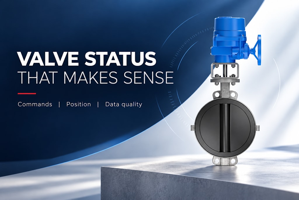
A monitoring interface needs to distinguish the requested action, measured position, local or remote authority, movement, faults, and data freshness. That distinction lets the interface describe what is known without pretending a command is proof of a physical result.
This article uses simulated records to explain a read-only monitoring model. It does not connect to or control equipment. The goal is to help developers represent industrial device state accurately before adapting a model to the signals and operating rules of a real installation.
Begin with independent facts
An actuator can be at 42 percent travel, in local mode, stationary, and reporting a fault simultaneously. A single enumeration such as “open,” “closed,” or “error” cannot express those facts without losing information. Build the model from independent fields and derive a concise display summary from them.
Separate requested position from measured position. A requested value belongs to the command or control layer. A measured value belongs to the device-feedback layer. Even when the two numbers match, they should retain distinct names and timestamps because they originate from different events.
Also distinguish position from process flow. A display of 42 percent travel says nothing precise about the percentage of rated flow. The relationship depends on the valve and pressure conditions. Developers should not add a flow estimate merely because a position value is available.
Define a compact read-only record
A useful simulated record might contain an equipment identifier, requested position, measured position, open and closed indications, local selection, running status, fault codes, source timestamp, and quality. Fields can be absent when the device does not provide them; absence should remain explicit rather than replaced with a plausible default.
For example, requestedPositionPct could be 60 while measuredPositionPct is 43. localMode could be false and running could be true. That record describes a valve apparently traveling toward a request, provided the relevant data is current. It does not establish that the valve will reach its target or that the process is receiving the expected flow.
The electric valve actuator operation and feedback background helps connect these field names to the physical equipment. The actual device’s signal definitions remain authoritative when the simulated model is later mapped to an installation.
Field
Simulated value
Meaning
assetId
CV-204
Stable equipment identity
requestedPositionPct
60
Requested travel
measuredPositionPct
43
Reported travel
localMode
false
Remote authority not locally excluded
running
true
Reported movement-related status
quality
good
Current value considered usable
sourceTime
2026-01-15T10:00:12Z
Illustrative source timestamp
Model unknown as a real condition
If measured position becomes unavailable, setting it to zero creates false information. Zero is a valid position. Use a missing value together with an explicit quality state, or retain the last valid value while clearly marking it as stale. The interface should make the distinction visible.
OPC UA’s DataValue concept separates a value from associated status and timestamps. That is a useful design principle even when the application uses a different transport. A measurement is more than a number; its usability and time context determine how it should be interpreted.
Choose freshness rules from the application’s expected update behavior. A two-second delay may be normal in one read-only display and unusual in another. Do not hard-code an unexplained universal timeout and present it as an equipment property. Keep the threshold configurable and document the reason for it.
Do not let the display hide contradictions
An open and closed indication asserted together may be invalid for a particular device mapping, or it may reflect a mapping or configuration issue. The interface should preserve the raw observations and flag the inconsistency rather than arbitrarily selecting the first state in a conditional statement.
Similarly, a reported position can disagree with an end indication. Before declaring a mechanical fault, consider scaling, timing, and signal definitions. The monitoring model should expose enough context to investigate the disagreement without claiming a cause it cannot establish.
A useful summary might say “position information inconsistent” while showing the relevant values and update times. That is more honest and more actionable than a green valve icon generated from whichever field happened to update last.
Represent a simulated movement over time
Consider an illustrative sequence. At time zero, the requested position changes from 20 to 60 percent. The measured position remains at 20 briefly, then rises through 35 and 48 before settling near 60. During movement, a command-position difference is expected.
If local mode becomes active before the change, lack of movement may be intentional. If feedback stops updating halfway through, the correct summary is uncertain or stale position information. If a fault arrives while position remains valid, the model should show both the known position and the fault.
This sequence reveals why one “command failed” timer is insufficient. Interpretation depends on operating authority, data quality, configured tolerance, and expected movement. The interface should show these conditions before presenting a simplified alarm conclusion.
Keep transport mapping outside the display logic
Industrial protocols carry values, but the meaning of a device’s registers, bits, and scaling comes from its mapping. Modbus, for example, defines protocol operations and data structures; it does not assign one universal register address to every actuator’s position.
Create an adapter that converts the actual device representation into the application’s semantic fields. Keep that mapping separate from the display component. The interface can then be tested with simulated records without depending on an invented register map or a live connection.
The adapter should preserve units, scaling, quality, and time information where available. If a source lacks one of those properties, the application should identify the limitation instead of fabricating it. A local receipt timestamp can be useful, but it is not necessarily the time when the device measured the position.
Design the screen around operator questions
The first questions are usually practical: Where is the valve? Is the information current? Who has control authority? Is movement occurring? Is a fault present? A clear layout can answer those before exposing less frequently used diagnostics.
Use labels such as “Requested position” and “Measured position.” Show local selection separately. Make stale or unavailable information visually distinct without relying only on color. Text and timestamps help prevent an outdated value from appearing to be a current equipment state.
The monitoring screen should not imply process isolation from a closed-position icon. If the application needs leakage or flow information, it needs an appropriate source for that information. A software model should respect the boundary between actuator state and the wider process.
Test the model with meaningful scenarios
Use simulated records for normal travel, stationary operation, local mode, stale feedback, contradictory indications, and a fault with valid position. These tests address real interpretation risks. A test that merely repeats the implementation’s field assignments provides less confidence than a scenario with a clear expected display meaning.
Also test out-of-order updates and missing fields. A late message should not quietly replace a newer value if the application has a reliable way to identify the order. The appropriate handling depends on the data source, but the decision should be explicit.
For physical context, ysmeter describes industrial valve equipment that can be represented by such monitoring systems. The developer’s responsibility is to map the available evidence accurately, without claiming a capability or measurement that the chosen assembly does not provide.
Separate source truth from presentation rules
The device adapter should preserve the raw meaning of the available signals, while the presentation layer decides how to summarize them for the reader. For example, the source may report a numerical position and a separate fault code. The interface can display a concise message, but it should retain access to both underlying facts and their time context.
Derived states should have explicit rules. “Traveling” might require a current running indication or a supported observation of changing position, depending on the device definition. It should not be inferred solely from a difference between demand and position, because that difference can also occur in local mode or after a blocked action. Naming the rule makes the display easier to test.
Keep simulation fixtures separate from real device configuration. A sample asset identifier, timestamp, or register-like field should not become an accidental production default. The read-only examples in this article illustrate data meaning; they do not establish a live mapping, polling interval, or permission to issue commands.
This separation also helps when the hardware changes. A new actuator can use a different protocol or set of diagnostic codes while the interface continues to work with the same semantic model. The adapter must be reviewed against the new device’s documentation, but the operator-facing concepts remain stable: request, measured state, authority, fault, quality, and time.
Frequently asked questions
Why not store one field called valveState?
A single field cannot reliably represent position, authority, movement, faults, and data quality at the same time. Keep those facts independent and derive a readable summary. This preserves information when conditions overlap or when one signal becomes unavailable.
Can the interface infer actual position from the last command?
It can display the last request, clearly labeled, but should not present it as measured position. The actuator may be unavailable, locally controlled, or mechanically unable to move. A command is an intention rather than evidence of movement.
Does Modbus define the position register for every actuator?
No. The device mapping defines which addresses and formats represent its data. The protocol specification does not provide a universal actuator register map. Use the actual device documentation when implementing an adapter beyond the simulation stage.
Should a fault clear the last valid position from the screen?
Not automatically. Position and fault are separate facts. If the position remains valid, show it with the fault. If it becomes stale or invalid, mark that quality change explicitly. The display should communicate the evidence rather than hide it.
Build the interface from independent facts and simulated edge cases first. That creates a clearer foundation for later integration and avoids confusing software intent with physical equipment state.
References
[1] OPC Foundation. OPC Unified Architecture, Part 6: Mappings — DataValue.
[2] Modbus Organization. MODBUS Application Protocol Specification V1.1b3.
[3] Rotork. IQ3 Pro.
About the Creator
Enjoyed the story? Support the Creator.
Subscribe for free to receive all their stories in your feed.
Comments
There are no comments for this story
Be the first to respond and start the conversation.