
How a Self Operated Pressure Control Valve Uses Process Energy
A self-operated pressure control valve with pilot can regulate pressure without an external motor or instrument-air supply

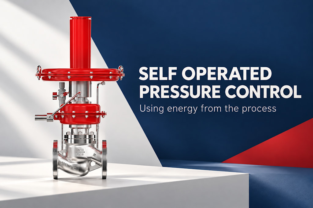
because the process fluid provides the energy for its regulating mechanism. Pressure acting on a sensing element is compared mechanically with a set force. The pilot then influences the pressure acting on a main actuator, which changes the main valve opening.
“Self-operated” does not mean that the valve creates energy or works independently of the process conditions. It needs a suitable pressure environment and flow capacity, and it responds to the pressure its sensing arrangement detects. Understanding that distinction makes the technology easier to select and prevents unrealistic expectations about what happens when supply pressure disappears.
Begin with pressure acting on an area
Pressure produces force when it acts over an effective area. In a regulator, a diaphragm or another sensing element can convert a pressure change into mechanical movement. A spring or other loading arrangement provides an opposing force related to the desired setting.
For a simple illustration, 2,000 pascals acting over an effective area of 0.01 square meter produces 20 newtons of force. The arithmetic is pressure multiplied by area. This is a conceptual example, not a calculation for the ZZYP-II or a substitute for the geometry and force balance of a real regulator.
The example explains why a modest pressure can still produce useful sensing force over a sufficiently large area. The regulator’s detailed behavior also depends on spring characteristics, friction, fluid forces, and the movement needed to change the opening. Those factors are designed together rather than added afterward.
Direct operation links sensing and valve movement
In a direct-operated arrangement, the sensing and loading forces act more directly on the regulating element. As downstream demand changes, pressure changes and the mechanism moves to establish a new operating balance. The resulting pressure is therefore related to flow and the design’s operating characteristic.
The movement required to open the valve can change the spring force and other forces in the balance. This helps explain why a regulator does not necessarily hold one exact outlet pressure at every flow. Its pressure-flow behavior must be considered over the required operating range.
This mechanism can be simple and useful for appropriate duties. Simplicity is a functional advantage when the required capacity and pressure variation are acceptable. It does not make direct operation universally preferable, just as adding a pilot does not make every application automatically better.
The pilot controls the main actuator
A pilot-operated design introduces a smaller regulating mechanism that influences the pressure loading of a larger main actuator. The main valve carries the required process flow, while the pilot performs part of the sensing and control task. This arrangement can support useful regulation over duties that are demanding for a direct-operated mechanism.
The exact circuit varies. Some designs load a diaphragm chamber in one way; others use different pressure paths and restrictions. Do not infer the detailed connection arrangement of one model from another manufacturer’s illustration. The common concept is that a small pressure-control action influences the force available to position the main valve.
YSMETER describes its ZZYP-II as a self-operated pressure control valve with pilot. That designation identifies the product’s regulating approach. Its actual use still depends on the selected configuration, controlled medium, pressure conditions, and required operating range.
Follow a change in downstream demand
Imagine a hypothetical gas line supplying equipment at a controlled downstream pressure. When the equipment draws more gas, downstream pressure tends to decrease. The regulator senses that change and responds by increasing the main flow path, within its available capacity and operating conditions.
When demand falls, downstream pressure tends to rise and the mechanism responds in the opposite direction. The system settles at an operating point determined by the regulator and connected piping. The pressure at that point need not be identical to the setting established at a different flow.
This sequence explains the regulating principle without assuming a particular internal pilot circuit. It also shows why a regulator cannot compensate indefinitely for an undersized upstream supply. If adequate pressure and flow are not available at the inlet, opening the main valve further cannot create them.
Know which side is being controlled
A pressure-reducing regulator controls downstream pressure by admitting flow from a higher-pressure source. A backpressure regulator controls upstream pressure by allowing flow away when the upstream pressure rises. Both use pressure feedback, but their control objectives differ.
Selecting the wrong function is more fundamental than choosing the wrong size. A device that responds to upstream pressure cannot be assumed to maintain the desired downstream pressure in the same way. The process description should state the controlled side and what the valve should do when that pressure rises or falls.
Function
Pressure being controlled
Typical regulating response
Pressure reduction
Downstream pressure
Admit more flow when controlled pressure falls
Backpressure control
Upstream pressure
Release more flow when controlled pressure rises
External sensing
Pressure at a selected connection
Respond to that sensing location
Main actuator loading
Force available to move the main valve
Follow the pilot circuit’s design
No external drive does not mean no limits
The main valve and pilot arrangement need suitable pressure conditions to function as intended. Depending on the design, minimum differential pressure can be important. Capacity also depends on gas properties, inlet conditions, and the selected internal flow path.
Contamination can affect small passages and moving parts. The medium and any conditioning requirements should therefore fit the selected construction. A self-operated device may reduce the need for external utilities, but it still needs an installation that preserves the intended pressure and sensing paths.
Temperature and material compatibility remain relevant. The absence of an electric motor does not make the valve suitable for every gas or temperature. Seats, diaphragms, packing, and other wetted components must match the defined medium and operating conditions.
Separate regulation from protective functions
A regulator controls pressure during its intended operation. It should not automatically be treated as every protective device a system may require. The system’s response to an abnormal supply condition, blocked sensing path, or internal failure must be considered separately where those conditions affect the design.
Similarly, losing external electrical power does not necessarily stop a self-operated regulator from responding to process pressure. Losing the process pressure that supplies its operating energy is a different event. The resulting valve behavior depends on the construction and pressure conditions, not on the general label “self-operated.”
This distinction belongs in a concise functional description. State what the regulator controls normally and what other arrangements address abnormal conditions. Clear boundaries are more useful than broad claims that a mechanism is inherently safe under every failure.
Select from an operating envelope
Define the gas, flow range, inlet-pressure range, desired controlled pressure, temperature, and acceptable pressure variation. Identify the sensing location and control direction. Then compare the proposed regulator with those paired operating cases.
YSMETER offers self-operated and externally actuated valve options. The choice should follow the control task. A self-operated arrangement can be attractive when local pressure regulation is sufficient and the process provides suitable energy, while a wider automation task may require other instrumentation or actuation.
An effective selection note explains why the regulator’s local mechanical feedback is appropriate. It should also identify any limits, such as changing demand or supply conditions that require additional review. That note helps future operators understand the system rather than treating the adjustment screw as an unlimited solution to pressure problems.
Distinguish sensing energy from flow capacity
A regulator can sense a pressure change and still be unable to supply the requested flow. The sensing mechanism needs only enough force to respond, while the main flow path must pass the process demand under the available pressure conditions. These are connected tasks, but they are not the same capacity requirement.
Consider a hypothetical consumer that increases gas demand beyond the selected regulator’s usable capacity. The mechanism may respond in the expected direction by opening further, yet the controlled pressure can remain below the target. The observed low pressure does not automatically indicate a broken pilot or spring. It may show that the system has reached a capacity or supply constraint.
The opposite situation can also confuse diagnosis. At very low demand, a large main flow path may operate close to its closed condition. The resulting behavior should be compared with the design’s intended range rather than judged solely from its ability to pass a high peak flow. The selected regulator has to fit the useful operating envelope.
This distinction gives operators a more accurate way to interpret adjustment. Changing the set force can alter the pressure objective, but it does not create a larger upstream supply or remove every flow limitation. A pressure-setting change should therefore be understood as a control adjustment within a suitable application, not as a universal response to inadequate gas delivery.
Frequently asked questions
Where does the operating energy come from?
It comes from the pressure energy of the process fluid. The regulator redirects or balances that energy through its sensing and actuator arrangement. It does not generate energy, and it cannot supply pressure that is unavailable from the connected system.
Is the pilot an electronic controller?
In the self-operated arrangement discussed here, the pilot is a pressure-responsive regulating mechanism. A particular installation may include electronic monitoring or accessories, but those should not be confused with the basic mechanical pressure-control principle.
Can the same regulator control upstream and downstream pressure?
Only when the selected design and configuration support the intended function. Pressure reduction and backpressure control have different objectives. State which pressure is being controlled and how the valve should respond before selecting the configuration.
Does the pressure stay exactly at the setpoint at every flow?
No general guarantee follows from the self-operated principle. Actual pressure varies with the regulator’s operating characteristic and system conditions. Evaluate the expected flow range, supply variation, and acceptable pressure band for the specific application.
Use the energy and force balance to understand the mechanism, then select the actual assembly from its pressure-flow envelope. That connects a simple operating principle to a realistic application decision.
References
[1] Spirax Sarco. Self-acting Pressure Controls and Applications.
[2] Swagelok. How to Flatten a Regulator Flow Curve to Reduce Droop.
[3] Emerson. Industrial Regulators Quick Selection Guide.
About the Creator
Enjoyed the story? Support the Creator.
Subscribe for free to receive all their stories in your feed.
Comments
There are no comments for this story
Be the first to respond and start the conversation.