
Designing Thin-Wall LCP Parts Around the Flow Path
Liquid crystal polymer (LCP) is a good fit for compact parts with thin sections and demanding functional requirements, such as connectors and precision housings.

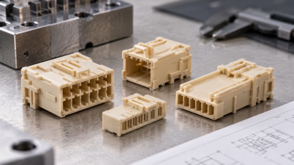
Liquid crystal polymer (LCP) is a good fit for compact parts with thin sections and demanding functional requirements, such as connectors and precision housings. But LCP is not one material with one set of properties. Celanese Vectra, is a family of grades, and reinforcement, flow behavior, color, and use conditions all change what a designer should expect. The mold layout has to account for how the specific resin you choose actually flows.
Why orientation changes the design conversation
As LCP melt moves through the cavity, its molecules line up with the flow. The result is directional behavior: shrinkage and mechanical response can differ along the flow and across it. That matters most in long thin walls, ribs, bosses, and near weld lines, where performance may vary depending on direction.
Because of this, gate location, runner layout, wall transitions, and the flow around holes should be reviewed together as one system rather than one decision at a time.
Map the cavity before the tool is cut
Trace the fill path from the gate to the last-filled region and ask three questions:
● Where do flow fronts meet?
● Where does the air escape?
● Does a knit line cross a loaded or functional feature?
Ask the mold designer to mark expected flow directions and meeting points directly on the part model. Then check those locations against loads, sealing surfaces, and electrical features. Keep wall transitions gradual, since abrupt changes complicate both filling and cooling. Gate changes may be needed to balance fill and orientation in a thin-wall design, but treat any prediction as a hypothesis to confirm in mold trials.
Look at weld lines in terms of function
A weld line can differ from the surrounding material in appearance and strength. How much that matters depends on the grade, the geometry, the process, and the direction of the load. A weld line on a cosmetic surface is a different problem from one that crosses a latch, a thin wall, or a seal.
Moving the gate can shift a weld line, but it may create a new risk somewhere else. The goal is to balance fill, venting, appearance, and the functional load path, not to eliminate every knit line.
Plan vents, transitions, and ejection together
Thin details can fill quickly and still trap air at the end of the flow path, leading to burns or short shots. Venting depends on gate size, runner balance, and injection conditions, so it should not be settled in isolation.
Ejection deserves the same attention. A slender core may need support, and a delicate rib can be damaged on release if draft or surface finish is inadequate. Specify where ejector marks are acceptable and where they are not. A geometry that fills well but releases inconsistently is still a problem.
Treat the grade as a design input
Before moldability discussions start, confirm the exact product code and the current datasheet. If anyone proposes switching grades to improve flow or availability, treat it as a design change that triggers a review of flow, orientation, shrinkage, and qualification. Two LCP grades cannot be assumed to give the same dimensions or mechanical response.
The same caution applies to published data. A value for one test direction or one grade should not be carried over to another. When you read the documentation for any Celanese LCP grade, use the figures that match your grade and molded orientation. If the datasheet does not answer a design question, mark it for testing rather than filling the gap with a family-level assumption.
Decide which dimensions matter
Not every dimension has equal consequence. Identify the mating datums, contact alignment, snap fits, and critical clearances, then measure at documented locations in a repeatable condition.
● If the part is sensitive to orientation, check dimensions in more than one axis.
● If temperature or moisture can affect measurement, inspect after a defined conditioning period.
● For very small parts, use a fixture that does not deform them.
● Confirm that the chosen method (optical, contact probe, or functional gauge) can actually resolve the tolerance.
Also separate cosmetic criteria from functional ones, so an acceptable knit line is not confused with a structural defect.
Build a validation plan around named questions
A first run should answer specific questions: Does the grade fill the intended geometry? Do critical dimensions stabilize? Does the interface perform in the assembly? Define acceptance criteria before anyone looks at samples, otherwise different reviewers may judge the same visible mark differently.
Record the material lot, mold revision, process settings, and inspection results, and label parts by cavity and gate condition so results stay traceable. Be realistic about prototype tooling too. A simple prototype tool may not reproduce production cooling, gating, or ejection, so prototype samples are good for fit and early learning but should not automatically qualify the production process.
Keep changes under control
If the resin grade, colorant, gate, vent, or wall dimension changes, reassess orientation and dimensional behavior, and note which requirements and tests are affected. Keep the approved sample, process records, and test evidence together with the drawing revision so production and quality teams work from the same assumptions.
Working with a molder
When you request a quotation, send the current drawing, resin grade and color, annual volume, critical dimensions, and operating environment. Ask about the tooling concept, expected gate and weld-line locations, and how inspection will be done. A good supplier explains its assumptions and proposed validation rather than claiming that a family name guarantees performance.
Before you release the tool
Confirm the grade identity and availability, the gate and vent assumptions, the critical dimensions, the expected weld-line regions, and how sample approval will be done. Ask what kinds of changes would trigger another review. Doing this before steel is cut is far cheaper than discovering the gaps afterward.
About the Creator
Enjoyed the story? Support the Creator.
Subscribe for free to receive all their stories in your feed.
Comments
There are no comments for this story
Be the first to respond and start the conversation.