
An Electric Valve Actuator Guide to Remote Operation
An electric valve actuator makes remote operation possible by converting electrical power into controlled movement at a valve stem.

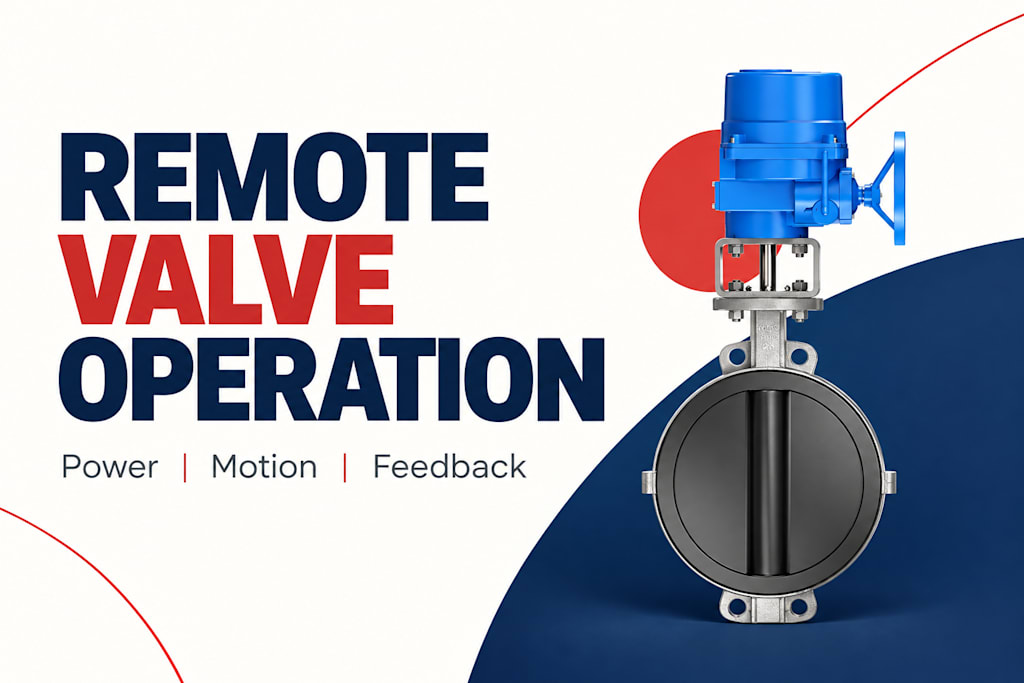
A motor supplies motion, gearing adapts speed and output, and local controls stop or position the valve. Feedback tells the wider control system what the assembly is doing. Sending an “open” instruction is therefore only one part of the job.
This electric valve actuator guide follows that chain from the control room to the valve and back. Understanding the chain helps engineers and facility managers separate a communication issue from a movement problem, and distinguish an actuator that can simply open a line from one intended to regulate a process repeatedly.
Follow the movement from motor to valve
The motor usually turns faster than the valve needs to move. A gearbox reduces that speed and increases available torque, subject to mechanical losses. The output can rotate a quarter-turn shaft, turn a multi-turn stem mechanism, or drive a linear arrangement. The correct form depends on the valve rather than the control room interface.
A butterfly valve typically rotates its disc through approximately a quarter turn. A gate valve generally requires multiple turns to produce linear gate movement. A globe control valve needs controlled plug travel. An actuator that physically fits a bracket is not necessarily capable of the right movement, output, or stopping method for all three.
The coupling completes the mechanical path. If the coupling slips or a stem connection fails, the motor may run while the valve remains still. This is why evidence of motor operation should not be interpreted as proof that the fluid path has changed. Position sensing must be understood in relation to the point where it is measured.
Separate power from instructions
The power circuit provides the energy needed to move the valve. The command circuit tells the actuator what to do. Depending on the assembly, commands may arrive as discrete contacts, an analog demand, or messages through an industrial communication system. The presence of a communication cable does not mean the motor can operate without its power supply.
For simple open-close duty, the interface may expose separate open, close, and stop commands. A modulating package accepts a requested intermediate position and compares it with measured position. Its controls then move the motor until the difference is within the configured operating band. That positioning task requires more than attaching an analog input to an arbitrary motor.
The electric valve actuator guide published by YSMETER provides a useful introduction to this equipment category. For a real project, the next step is to relate the chosen control interface to the actual valve movement and operating duty, rather than assuming every electrically driven valve has the same capabilities.
Understand what each feedback signal proves
An open limit contact usually indicates that a configured end-position condition has been reached. A position transmitter reports a value over the travel range. A running signal indicates that movement is being commanded or detected, depending on the device. A fault signal indicates an abnormal condition, but the detail available varies by actuator.
These signals answer different questions. A display showing 100 percent demand is displaying what the controller wants. A display showing 100 percent measured travel is displaying a position measurement. Neither alone proves that the valve is passing its expected flow. The process still needs its own pressure, flow, or temperature measurement.
Signal
What it describes
What it does not prove
Open command
Requested action
Valve has opened
Running status
Actuator activity
Fluid is flowing
Position feedback
Measured travel
Percentage of rated flow
Closed limit
Configured closed position
Leak-free isolation
Fault status
Reported abnormal condition
Complete mechanical diagnosis
Keep the display labels explicit. “Requested position” and “measured position” are more informative than two unlabeled percentages. Include the time of the latest valid update so a frozen value cannot quietly masquerade as a live measurement.
Local control changes who has authority
Many industrial assemblies offer local and remote operating modes. In local mode, commands from a control system may be blocked while a technician uses controls at the actuator. A remote command can then be transmitted correctly and still produce no movement. The issue is operating authority rather than a broken motor.
The monitoring system should therefore show local or remote selection separately from available power and position. If local operation is normal during maintenance, a “command not followed” message should explain that context. Otherwise, routine maintenance can create a stream of misleading alarms that makes real faults harder to recognize.
Manual operation is another distinct state. A handwheel may allow movement without motor power, but its engagement method and reporting behavior depend on the design. Do not assume that every electronic indicator stays current during manual movement or a power interruption. Check how the specific assembly measures and retains position.
Match the motion to the process
A remote valve does not always need to move quickly. A circulation line may benefit from a controlled closing time, while another process may need a faster response. The appropriate travel time comes from the process and piping behavior, not from a general preference for the fastest available actuator.
Frequency matters as much as duration. An actuator that makes two full strokes each day has a different thermal workload from one making frequent corrections throughout production. Motor starts, reversals, load, and ambient conditions affect duty suitability. Manufacturer duty classifications help distinguish these applications, but the actual operating pattern still needs to be described.
As a hypothetical example, compare a tank transfer valve that opens once per batch with a valve maintaining a changing outlet temperature. The transfer valve may spend hours at an end position. The temperature valve may make many small movements while remaining partially open. A similar-looking housing can conceal very different requirements for the motor and controls.
Define behavior when something is lost
Power loss, signal loss, and communication loss are separate events. An ordinary electric actuator may remain near its last position when motor power disappears. A system designed to move after power loss needs an appropriate stored-energy or backup arrangement. Position memory by itself is not energy for movement.
On loss of a command signal, a powered actuator may be configured to hold or move to a selected position. That setting must agree with the process design. A valve that should stop admitting fluid does not benefit from an interface that silently retains an outdated demand indefinitely.
These responses should be demonstrated during controlled commissioning with the process in an appropriate condition. Record what the actuator does, what the control room sees, and how normal control is restored. A diagram that shows only the normal signal path leaves important behavior undefined.
Make commissioning observable
Start by establishing the relationship between the valve’s mechanical travel and its electronic position range. Then confirm the direction of movement, end indications, local selection, remote commands, and fault reporting. Testing the command alone can miss an inverted or incorrectly scaled return signal.
For example, a simulated 50 percent demand should not automatically be accepted because the screen also reads 50 percent. The commissioning record should distinguish the transmitted demand, the feedback received, and the observed valve movement. Agreement among those independent observations is stronger evidence than matching numbers generated from the same variable.
Yongsheng supplies industrial valve solutions for applications where the complete assembly matters. When evaluating a package, connect the actuator’s electrical functions to the valve’s physical task and the operator’s need for understandable feedback. That approach makes remote operation easier to integrate and easier to diagnose later.
Trace a remote opening request through four checkpoints
Consider a hypothetical operator who requests an opening from a monitoring station. The first checkpoint is whether the control system accepted the request under its operating rules. The second is whether the actuator received an actionable command while remote authority and motor power were available. These are different events, and a screen acknowledgment should not collapse them into one success message.
The third checkpoint is physical movement. A running indication and changing position can support that observation, although their definitions must be understood. If the motor runs but position remains unchanged, the investigation differs from one in which the actuator never started. The record should retain both facts rather than summarize them as a generic communication failure.
The fourth checkpoint is the intended process result. A valve can reach its open position while a downstream blockage or unavailable pump prevents the expected flow. Position feedback has then done its job accurately, but it cannot answer the separate process question. The operator needs the relevant pressure or flow information to complete the picture.
This four-checkpoint view helps teams assign an issue to the right layer without guessing. It also makes a commissioning record clearer: request accepted, command available, movement observed, and process response established are separate observations. Not every installation needs a complex digital system to preserve those distinctions.
Frequently asked questions
Is an electric actuator the same as a motorized valve?
The actuator is the drive unit. A motorized valve is usually the assembled valve and drive. A complete package also depends on the coupling, mounting arrangement, travel settings, and control accessories. Buying the drive alone leaves those integration tasks unresolved.
Does fifty percent position mean fifty percent flow?
No. Flow depends on the valve’s characteristic and the pressure conditions in the system. A position value describes travel. Use a flow measurement or an appropriate hydraulic model when the application needs an estimate of actual flow.
Can remote operation work without a digital network?
Yes. Discrete wiring can provide open-close commands and status contacts. Analog signals can support intermediate positioning when the actuator is equipped for it. A digital network may add information and flexibility, but it is not required for every remote valve.
Why might a healthy actuator ignore a remote command?
Local mode, an active interlock, an unavailable motor supply, or a configured stop condition may prevent movement. Check the authority and readiness signals alongside the command. Repeatedly sending the instruction will not resolve an intentional operating restriction.
Map the power, command, movement, and feedback paths before choosing an actuator package. That map gives both the installer and the operator a clear picture of what successful remote operation should look like.
References
[1] Rotork. IQ3 Pro.
[2] AUMA. Actuators SA.
[3] OPC Foundation. OPC Unified Architecture, Part 6: Mappings — DataValue.
About the Creator
Enjoyed the story? Support the Creator.
Subscribe for free to receive all their stories in your feed.
Comments
There are no comments for this story
Be the first to respond and start the conversation.