
How CGI Characters Are Made (Part 1)
An in-depth look at the process of creating 3D characters for production.


If you're like me, CGI and VFX have been blowing your mind ever since Star Wars convinced you that epic space battles constantly rage across the cosmos. I say “ever since” because to this day my jaw still drops at the sight of the magnificent effects and characters being made by independent creators and large production companies alike. Those brilliant creations largely inspired me to pursue a career in design. When I look back at the period where my passions were being realized, I think about how much I would have appreciated having an in-depth look into how characters and scenes were made. So that's what I'm making here. Hopefully this series will help illuminate what goes into making the CG characters and worlds that inspired and bewildered our collective hearts and minds.
First Things First
There are endless paths to making CG characters. Choosing how to create one often depends on numerous factors like the purpose of the project, deadlines, and of course, personal preference. While I have my preferences, I will always try to offer up explanations and links when discussing some of the other methods and software creators use.
This post will take you through many of the core components of 3D design. We will start with making a base sculpt, then we’ll cover retopology, unwrapping and texturing, rigging and posing, and lastly rendering. But keep in mind this is only part 1. There is a lot of ground to cover and this will get pretty in-depth, but I will be diving deeper into these concepts in later posts as well. So if you enjoy this, keep an eye out for my next one.
Sculpting
Depending on the subject matter, 3D artists will use either a modeling software or a sculpting software to create the design. Generally speaking, organic forms like people and animals are sculpted, and hard surface objects like furniture, weapons, and machines are modeled. With that said, there are situations where the other is better suited to the task, and many models will require overlap between the two.
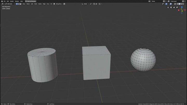
In the sculpt timelapse above, I start with a cylinder, and begin shaping it and adding resolution. But what does that really mean? Shapes like cylinders, cubes, and spheres are called primitives in 3D design, and they are made up of vertices, edges, and faces. Vertices are connected by edges, and 3 or more connected vertices can make a face (a.k.a. polygon). 3D models for production are made up of Tris (faces with 3 vertices) and Quads (faces with four vertices), with Ngons (faces with more than 4 vertices) being avoided. These elements can all be modified. In the clip below, I drag the vertex at the top of the cylinder up to make a cone, bevel the edges of the cube to smooth it, and extrude faces from the cylinder to make a ring. As you can imagine, there are tons of other tools to further manipulate a 3D object. For 3D modeling, I primarily use Blender. Some of the other widely used 3D modeling applications are Maya, 3DS Max, and Cinema 4D.
3D Sculpting works similarly to 3D modelling, in that much of the process is manipulating the vertices that make up a mesh to create new forms. But where modeling has tools to modify the mesh, sculpting has brushes. Some of the basic brush functions are used to add volume, carve crevices, and move parts around. The software I use for sculpting is called Zbrush, but there are other great alternatives like Mudbox and Blender.
Now if sculpting is essentially the manipulation of vertices, then the level of detail you can achieve will always be tied to the number of vertices the object has. So in order to get more detail out of the sculpt, we have to increase the number of vertices (a.k.a. resolution). Zbrush offers several ways to do this, and during my sculpt I used Dynamesh and Sculptris. In the clip below you can see how activating dynamesh increases the resolution of the entire sphere, while Sculptris increases resolution in the areas the brush goes over. Together these functions allow designers to quickly build up and iterate on their model.

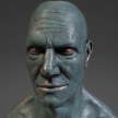
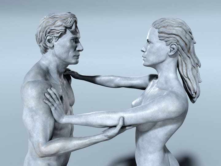
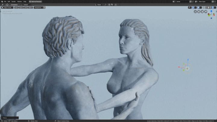
With all of these tools, and a healthy understanding of human anatomy, the sculpt can begin. First the basic forms and proportions are established, then the secondary forms like the muscles, fingers, eyes, nose, and mouth. Lastly skin detail like pores and wrinkles are added, but I will talk more about how that is done in another post. For this example, I created the male from basically nothing, but often for film and video game production, artists will start with a base mesh to save time. In a similar vein, I created the female by modifying and re-sculpting the male. Check it out below.
Retopology
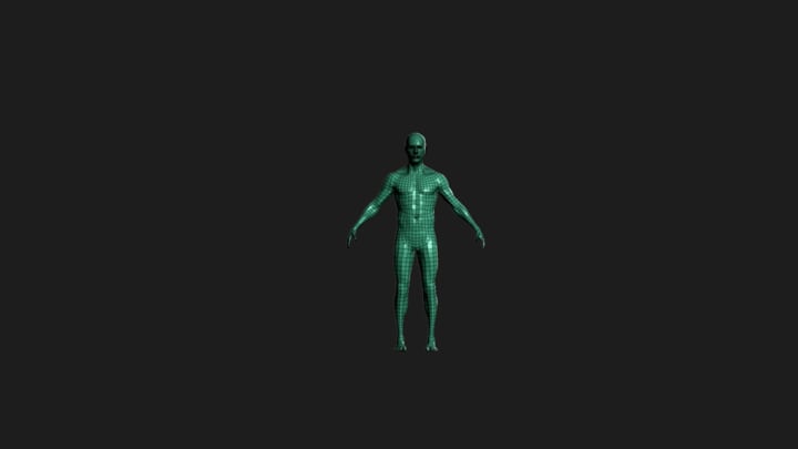
Now we have a high resolution mesh with a lot of detail. While that's great for a still render, the current state of the model is not usable in production. A mesh with this many vertices is very hard to manipulate or animate. The topology of the model is also a mess. In 3D design, a model's topology refers to its layout of polygons as well as the flow of its edges. This section is about changing the topology of the model from the layout on the left to the layout on the right, in the image above. There are numerous benefits to having clean topology which I'll get to as we go through the process.
Retopology is a lot like solving a jigsaw puzzle which you create as you solve. It starts off quite fun, but as you reach the final connections and scramble to figure out the best directions to send these errant edges, it has the potential to boil into a living nightmare you can't wake up from. With that said I actually really enjoy it.
During retopology, you create and connect vertices which snap to the surface of the model, effectively overlaying a completely new topology layout while maintaining the shape of the original. Most 3D modeling software have retopology capabilities. While many of them offer a suite of tools to increase the efficiency of the process, everyone has their preference. I’ve seen veteran 3D artists retopologize whole models vertex by vertex with no extra tools whatsoever. Hats off to them. I use an add-on for Blender called RetopoFlow. You can see some of its tools in the clip below. Other great alternatives include 3D-Coat, Topogun, and Maya. In some cases, retopology may be too time consuming. So alternative workflows like ZWrap's topology transfer are used instead.

The biggest benefit to clean topology is that it offers much more control over the resolution of the mesh through the use of subdivision levels. In the previous section we talked about how Dynamesh and Sculptris can increase the resolution of the mesh, but neither method was particularly clean. Using subdivision levels, we can easily adjust the resolution of the mesh to be higher or lower while preserving the detail.
Without getting too technical, subdividing a mesh converts each polygon into several smaller, equally sized polygons by adding new vertices, and connecting them with new edges. This effectively turns 1 polygon to 4 (or 3 if the polygon was a Tri). In the clip below, a square plane is subdivided 6 times, going from 1 face to 4096 faces. Tris and Ngons are often avoided in a subdivision workflow, as they produce less predictable and clean topology than quads do.

Once the mesh has been completely retopologized, it is brought back into Zbrush. Here the low poly mesh is subdivided multiple times, during which the detail from the sculpt is transferred over to the new mesh. Now the mesh can be worked on at any subdivision level. For instance, while the sculpture of the male had over 20 million vertices, the finished model for this project was kept on subdivision level 3, where it had only 90,000 vertices. Generally video game models require lower polygon counts than models made for film. The reason for that will be explained in the Rendering section.

Texturing and UV Unwrapping
Texturing CG models is the process of applying shaders and materials that will tell the render engine how to represent each pixel. If you have ever watched a behind the scenes video where a CG character is shown in a dozen different colorful overlays, you likely thought it was cool but had no idea what you were seeing. Each one of those is a different texture map used to create the finished look of the 3D model. After going through this section, you should be able to pick several of them out next time you see them.
First we need to talk about shaders. Every CG Model in a film or video game has one or more shaders attached to it that dictate how light affects it, and how the virtual camera renders it. Shaders are what decide whether a video game world looks hyper realistic like Modern Warfare, cartoonish like Borderlands, or cel-shaded like Breath of the Wild. For the purpose of this post, we are only going to talk about how realism is achieved using shaders.
In order to achieve realistic visuals, the VFX industry has largely adopted a Physically Based Rendering (PBR) pipeline. In the PBR pipeline, the shader adheres to realistic shading and lighting behavior while using various texture maps to tweak values like roughness, specularity, and color. Since many different programs use the PBR pipeline, materials can be viewed in different software and still maintain a consistent look. If you are interested in learning more about how Physically Based Rendering works, check out the first half of the video below, or the this write-up. These VFX veterans can explain the concept more thoroughly than I do.
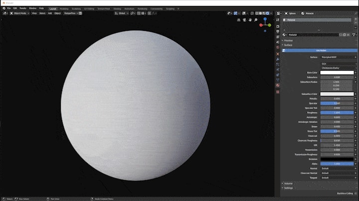
A standard PBR shader consists of sliders which allow you to adjust attributes like roughness, specularity, and color. But most real-world objects have variation to those attributes. Wood is multicolored. A dirty table is less reflective where the grunge has built up. In order to give an object those variations, we can use texture maps, which are plugged into the shader’s sliders. Texture maps are simply flat images with color information. Below you can see a sphere shader's color, roughness, and metalness being tweaked before several wood texture maps are added. First the base color map (a.k.a albedo) is applied, then the roughness map, then the normal map.
So what are these maps? Where do they come from? Maps can come from photos and images or they can be made procedurally using pattern generators. Some maps are made from a 3D models shape through a process called baking. Below is a clip showing some the most commonly used maps, with descriptions of each one beneath.
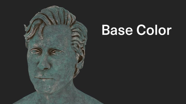
Base Color Map - The color info for the 3D model without any reflectivity or lighting information.
Roughness Map - The roughness info decides how much light is reflected off every part of the mesh. Black parts are not rough and will be very reflective. White parts are completely rough and will not reflect light.
Metalness Map - The Metalness info devices which parts of the 3D model are metal, and which are dielectric. Metal objects react differently to light and need to be identified on the mesh. The metalness map works together with the roughness and base color to create realistic color and reflections across the model. An alternative to the Metalness/Roughness workflow is the Specular/Gloss workflow. If you would like to learn more about the differences, click here.
Normal Map - Normal maps add surface details like bumps and dents that are accurately affected by lighting without actually changing the surface of the 3D Model or requiring more vertices. In the retopology section, I mentioned that while the finished sculpt was 20 million vertices, the mesh used for texturing had only 90 thousand. By using normal maps, lower poly meshes can imitate the level of detail found in the high poly mesh. The process of transferring detail from the high poly mesh to the low poly is called baking.
Ambient Occlusion Map - Ambient occlusion maps show how the model would be lit without a direct lighting source. The darker parts delineate the more occluded areas, where light would not be able to reach as easily. Ambient occlusion is used often in the texturing process, as well as in video games, where lighting needs to be faked or baked.
These maps were made in Substance Painter, a texturing software. In Substance Painter, a 3D model is imported into the scene. Then several texture maps are baked onto the model using a high poly reference when possible. After the maps have been baked, various colors, patterns, and painting layers can be applied to the mesh to create different materials like wood, rusted metal, or even realistic skin. The material I used for this project was created from scratch. Alternatively, Substance offers a massive material library to pull from.
Before a model can be imported into a texturing software, it has to be unwrapped. Unwrapping a 3D model is the process of creating seams across the surface which allow the model to be presented in 2D. This way 2D texture maps can be overlayed on top of it. The texture maps are then applied to the 3D mesh based on the location of each face in 2D. That might sound confusing so bare with me. In the clip below, the retopologized male is morphed from its 3D shape, to its unwrapped 2D layout based on the seams I created for it. Being able to unwrap a mesh along predictable edges is another reason why retopology is so important. I used Blender for unwrapping on this project, but it can be done in most of the applications I have mentioned so far.
The next clip should further explain the process of applying a 2D texture map to a 3D model. In it, the 3D model of the male appears on the left side, with the seams marked in red. The unwrapped model appears on the right side. A checkerboard texture is then fed into the shader as well as inserted beneath the unwrap. Wherever the unwrapped model is located on top of that texture is where the texture will be applied on the 3D mesh. Notice how moving and resizing the 2D chest will move and resize the grid on the 3D model.

One caveat to this method is that the mesh can only have as much data as a single texture. In order to get around this, CG models will often spread their unwrap data over multiple 2D grids, like the one on the right side below. Using multiple grids (a.k.a UDIMs) is crucial for creating highly detailed models. The finished male and female mesh’s for this project each have 4 UDIMs.
Working from the end of this section to the beginning we can see the texturing process in full. First, a 3D model is unwrapped in a 3D modeling software. With the model unwrapped, it can be imported into a texturing program. The materials are then created and exported out into a 3d modeling program, rendering program, or game engine. There they are plugged into a shader that is attached to the same 3D model.
Rigging and Posing
In order to pose or animate the mesh, it needs to be rigged with an armature. This is the process of creating a skeleton within the mesh that can deform and control each part. While a basic rig can be as simple as a single layer of bones, similar to a human skeletal system, advanced rigs will have multiple extra bones to effectively tweak the mesh. I will go over what these extra layers do as we get deeper into this section.
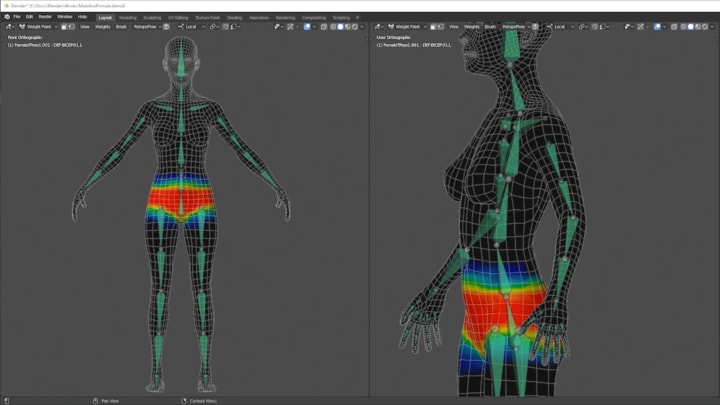
To make a basic armature, bones are placed throughout the model, taking care to make sure the joints line up with the body’s points of rotation (ie elbow, knee, finger joints). The mesh is then parented to the armature, which applies skin weights to all of the vertices in the mesh. Essentially each vertex will be affected by its nearest bone, and the bones level of influence over the vertices is based on the intensity of these skin weights. In the clip below you can see how the vertices around each bone have a color value, with red meaning it is completely influenced by the bone, and black meaning the vertex is not influenced at all. This means that if the bone were to move, all the red vertices would move the same amount and in the same direction, while the black vertices would not move at all. When multiple bones are affecting the same vertex, influence is decided by which bone has a heavier color painted on the vertex. Weight paints are tweaked throughout the rigging and posing process.
Now we have a rig that is perfectly adequate to pose, but not practical for animation. That is because to move any part of the mesh right now, we have to do it one bone at a time. Imagine if you had to reach out and grab something, but could only move one bone at a time. You would have to extend your arm out, rotate your elbow, then rotate each individual finger until it is locked around the object, then retract your arm back...anyway you get the point, this isn't scalable.
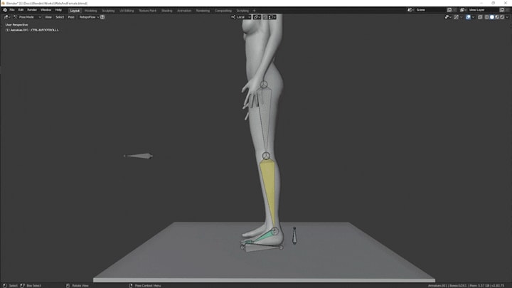
If more flexibility in the manipulation of the mesh is required, Forward and Inverse Kinematics (a.k.a. FK and IK) can be utilized. FK and IK refers to the direction of influence that a bone has over the bones in its chain. As an example, there are four bones in the leg rig chain: the thigh bone, shin bone, foot bone, and toe bone. The foot is connected to the shin, and the shin to the thigh. In a Forward Kinematic chain, which is a rig's default behavior, the bone at the top of the chain, in this case the thigh, will dictate the movement of the other bones. That means that if the thigh were to lift up, the shin and foot would lift too. But if the foot were to move, the shin and thigh would not. While this makes logical sense, as if you were to raise your knee up right now, your shin and foot would rise as well, it is not always practical for animators.
Consider the task of making a walk animation. When we walk, our feet lead the way. The foot rises off the ground then extends forward, leading the shin and thigh, before it drops back to the ground. This method of movement, where the bottom of the chain dictates the motion of the rest, is known as Inverse Kinematics. Being able to switch between FK and IK when manipulating the arms and legs of a mesh is a crucial part of animation. The clip below should help demonstrate the difference between the two. In it, the left leg is using Inverse Kinematics, and the right leg is using Forward Kinematics.
Various other new bones are also added to more efficiently control the mesh. For instance, bones are added to the hand to control all the fingers at once, making closing and opening the hand easier. With the rig complete, and various extra bone layers in place to better manipulate the mesh, it is ready to be posed.
While I made this rig from scratch in Blender, there are other tools and add-ons that are just as well suited to the task, if not better. Maya is currently the uncontested king of 3D animation, and 3DS max is more than capable as well. If time is of the essence, Blender's Rigify add-on and Maya’s Quick Rig tool expedite a lot of the early steps in this process.
Lastly, if you have ever looked into animation before, you may have noticed in behind-the-scenes clips, that rigs can get even more complex. Some have colored shapes instead of bones or have entire muscle systems. I will get more into that in a later part of this series, but for now i'll just mention that those shapes are created to replace the visual representation of the bones for easier editing, and that the muscle systems are advanced simulations running beneath the mesh to add more realistic deformation.
Rendering
CGI for film is rendered very differently than it is for video games. Movies, being a pre-recorded stream of images, can render a single frame over the course of hours, if not days. Video games must respond to player inputs which will constantly update what is on screen. Because of this, a video game renders its scenes in real time. This section will explore the primary differences between the two rendering techniques.
The virtual cameras that render CGI scenes for film and television use a process called path tracing. Path Tracing renders a frame similarly to how real world cameras capture an image. Before we continue, if you would like to hear Disney Animation Studio’s cartoony explanation of path tracing rather than mine, watch this video. If not, then read on.
In the real world, light sources emit rays of light in the direction they are pointing, which then hit various objects in the world. Depending on the roughness and metalness of these objects, the light is either absorbed, brightening the object, or redirected out again. Cameras have a sensor in them that when exposed to these light rays, analyzes the color value of that light and assigns it to a pixel. They do this for every pixel that the final image has.
In the digital world, these light sources work similarly, but the processing power it would take to compute all of these rays of light is far too intensive. Instead path tracing reverses the process. The camera fires out rays in search of light information. If it finds anything, it will follow the light bounces back to the light source. This way, the renderer only pays attention to the lighting that is relevant to the camera. Below you can see a path tracing renderer being re-positioned and putting together the image.

One of the beneftis of path tracing is that by paying attention to how light bounces around the scene, it can create more realistic lighting than a real-time renderer. A real time renderer has to fake its lighting. While lighting will in many cases look convincing, there are several missing features that set it apart from path tracing renders. Light rays are not calculated, so there is no light being bounced around the scene. Real-time renderers can actually get around this by baking the lighting. If you recall from the Texturing section, baking is the process of applying detail from one object to another. In this case, baking shadows and global illumination is the process of analyzing the scene, and identifying how light would actually react with the surfaces of the objects. Since the bake is done before runtime, the realistic lighting is stored in memory and can be kept on during camera and light movement. Unfortunately, this can only work with objects that do not move, as baking is too computationally heavy to do every frame.
If you have ever wondered why reflective surfaces like mirrors in video games will often not reflect the player, but will reflect the background, it is because only the surrounding area was baked with global illumination. Games getting around this will often have to create a duplicate of the player character which exists inside the mirror just to get it to work. In the below clip you can see a real time renderer moving around the scene. Notice how updating the view has no effect on the camera's ability to update the render of the scene immediately. Of course, it still looks very realistic. We only noticeably lose realism when it comes to light sources not realistically illuminating the world or when objects are not accurately reflecting the surrounding environment.
If you have been paying attention to Nvidia's real-time ray tracing advances, or are lucky enough to own an RTX supported graphics card, you have probably noticed just how lacking traditional video game rendering really is. That's not to say that video games today don't look beautiful, RTX or otherwise. But reaching a point where realistic light behavior is standardized in video games is one of the last bastions needed to be overcome.
The quality of lighting isn't the only thing video games have to sacrifice in order to achieve real time capabilities. Video game characters and environments also have fewer polygons and texture sets. Where a single game character is lucky to have 2 texture sets, CG characters for film are much more flexible.
With the camera positioned, the model textured and posed, and the lights set up. The scene is ready to be rendered with the click of a button. The animation at the beginning of this section is rendered in real time, and the final still renders for this project were rendered with path tracing. All rendering was done in blender. Some of other notable render engines to check out are Arnold, Vray, and Marmoset Toolbag (real-time).
Last Things Last
So that's how a CG character is made from start to finish. While that probably seemed like a lot, because it was, there is still much more to talk about. In Part 2 I will be going over how realistic skin, hair, clothing, armor, and maybe even weapons are made. As a graphic designer and freelance 3D artist, I’m always interested in new projects and inspiring ideas. So if you have any of those and are interested in working together, feel free to reach out! If you want to see the final renders for this project, you can visit my ArtStation.
See you guys in Part 2!
About the Creator
Jacob Frommer
Designer/Developer working in 2D and 3D
Keep reading
More stories from writers in Geeks and other communities.
How Sailor Moon Impacted My Life
For 30 years, this cosmic crybaby has warmed the hearts of many people inspired others, and still never fails to give people, courage, strength, and love. You could throw a dart at any movie, TV Show, or author that Sailor Moon has inspired.
By Samantha Parrish4 days ago in Geeks


Comments
There are no comments for this story
Be the first to respond and start the conversation.