
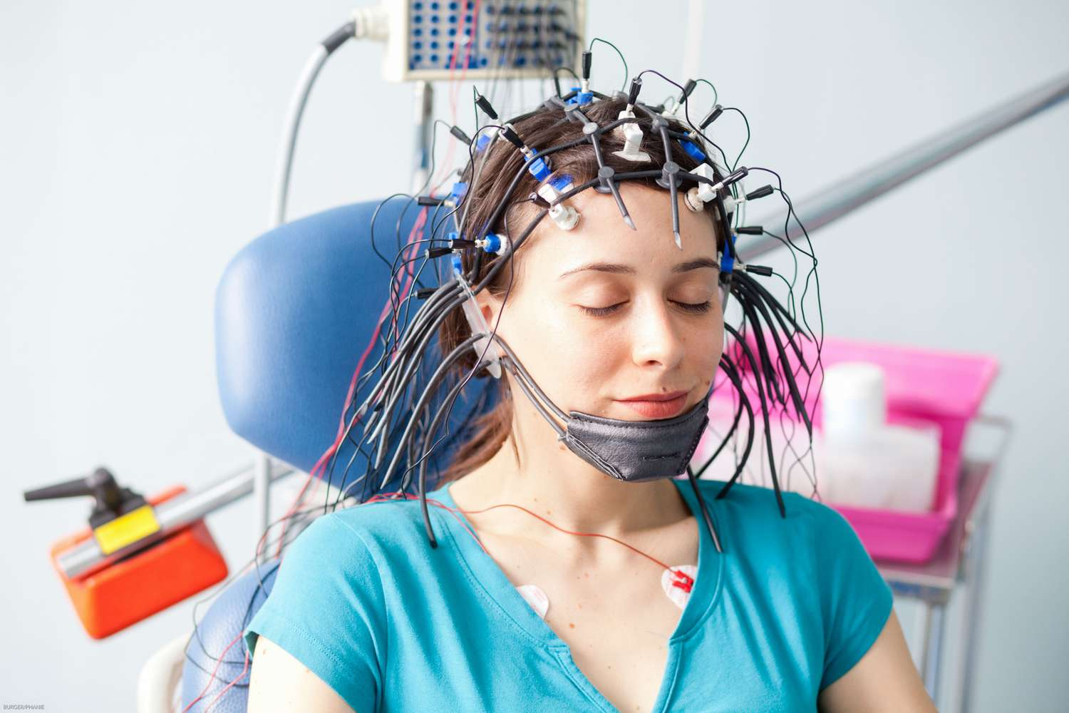
In currently available EEG machines, simple amplifiers are located in the jack box instead of differential amplifiers which are located in the machine itself. From the jack box, the EEG electrode inputs are connected to montage selector board which is a two- dimensional array of push buttons. Each row contains one button per jack box input. Vertically the array is organised into channels having two rows of buttons per channel. Each channel's output is equal to the voltage of the electrode selected in row 1 minus the voltage of the electrode selected in row 2. The top input of the pair is sometimes referred to as grid 1 or input 1 and the bottom grid 2 or input 2. One electrode can be an input to more than one channel. With 21 electrodes and 16 channels there are 2116 or 1.43 x 10²¹ possible montages. This impractical number necessitates some selected number of montages. Once a montage is selected, it may be programmed into the EEG machine so that it may be executed by a single switch selection.
AMPLIFIERS
From the montage selector, the EEG signals go to the amplifiers. The amplifiers of EEG machine are compound devices and should be distinguished from an amplifier whose only function is to increase voltage. The EEG amplifiers also have filters, voltage dividers, input and output jacks and calibration devices. The amplifier multiplies an input voltage by a constant. As the EEG signals are small, therefore, the constant range from 2 to 1000. Step down amplifiers are also available The amplification factor is referred to as gain and may be expressed as V/V out' in'
The amplifiers are designed to receive input voltages within a certain range known as dynamic range Input smaller than this range may be lost in the background noise.
Voltage higher than maximum input may cause damage to the equipment and distortion of signals.) Flexible control of the dynamic range is achieved with sensitivity. setting of the EEG machine. Sensitivity has the unit of mV/cm or uV/mm and is defined as the amount of voltage required to deflect the recording pens a given distance. A typical =sensitivity of the EEG machine is 7 µV/mm resulting in pen deflection of 3-20 mm of typical EEG input voltages. Electro- cardiogram may require a sensitivity of 1- 10 mV/cm. In practice, the sensitivity of EEG machine is adjusted so that the signal of interest produces a pen deflection, which is large enough to be read but not so large so as to collide with nearby channels. The gain of the recording is important and should be mentioned for proper interpretation. Usually the EEG recordings are obtained at 70 μV/cm.
The EEG amplifier itself has a frequency response, which is linear over a wide range of input voltages. In practice, the filter settings are determined by the range of linear frequency response. It is important to choose an amplifier whose frequency response is linear over the expected range of input voltages so that high or low frequency components are not distorted; therefore, EEG amplifiers differ from evoked potential amplifiers. The montage is known as referential when inputs from each channel are kept isolated from the system ground and a distant electrode is chosen as a common reference for several channels. The term monopolar is inappropriate since a voltage must always be recorded between two points. Montages linking nearby, electrodes are called bipolar and are less disturbed by noise. Both referential and bipolar montages are used in clinical practice. Differential montages are more sensitive to regional changes in EEG potential. Differential amplifiers cancel out the common mode signal. The common mode amplifier ratio refers to rejection of in phase and amplifying out of phase potentials. Good EEG amplifiers have common mode rejection ratio of at least 1000 and may be even as high as 10,000 or 100,000. The reference electrode is placed reasonably close to the recording electrode, which cancels out major noise signals. If the reference electrode is placed at distant location such as leg then it may act as antenna and pick up signals that may exceed the common mode range of amplifiers.
This convention is responsible for phase reversal of EEG signals by which negative signals can be localised to an electrode demonstrating phase reversal between two channels; e.g. in bipolar montage, channel 1 represents the differential voltage between Fp, and F, electrodes and the channel 2 demonstrates the differential amplitude from F, and T, electrodes. Since the pen deflects down in channel 1, F, is negative with respect to Fp As the pen deflects up in channel 2 F, is also negative with respect to T, AF, there is a local maximum extracellular negativity. The electrodes common to the two channels showing phase reversal may be presumed to be near the origin of seizure discharge (Fig. 2.6). Such extracellular negativity occurs during interictal spikes adjacent to the seizure focus as a result of sudden influx of sodium and calcium into the depolarising neurons. Many other EEG events including normal brain activity are the x result of local extracellular negativity. Extra- cellular positive potentials cause phase reversal with phase deflection away from each other in adjacent channels. Phase reversal is only applicable to bipolar montages.
Output of one amplifier may be used as input to the other. This allows a series of amplifiers each with a limited dynamic range to boost the EEG signal substantially. As the signal becomes amplified it becomes larger than the ambient noise; therefore, a differential amplification may no longer be required. Internal amplifiers may hence be single ended, i.e. one active input measured with respect to ground.
EEG FILTERS
Once the signals are subtracted and amplified, the output is filtered to remove specific frequency components. Filters are used to exclude unwanted signals from the EEG so that the waves of interest (1-30 Hz waveforms) are recorded clearly and without distortion. The filters affect any component of EEG to the extent that it rises or falls wit…
High frequency filter that reduces the amplitude of fast wave.
3. Notch filter that selectively reduces amplitude of 60 Hz electrical artefacts.
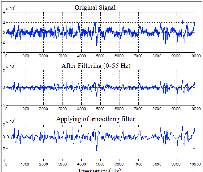
Low frequency filter is also known as high pass filter as it allows the higher frequencies to pass through the amplifier to the pen writer without attenuation. The high frequency filter is also known as low pass filter. Narrow band filter or 60 Hz filter allows higher and lower frequency wave forms to pass without significant attenuation. Each of these three filter actions is usually provided by individual channel controls permitting different selections for each channel and by master switches allowing selection of the same setting for all channels. The ideal EEG recording is to minimise the use of filters
About the Creator
Enjoyed the story? Support the Creator.
Subscribe for free to receive all their stories in your feed.
Comments
There are no comments for this story
Be the first to respond and start the conversation.