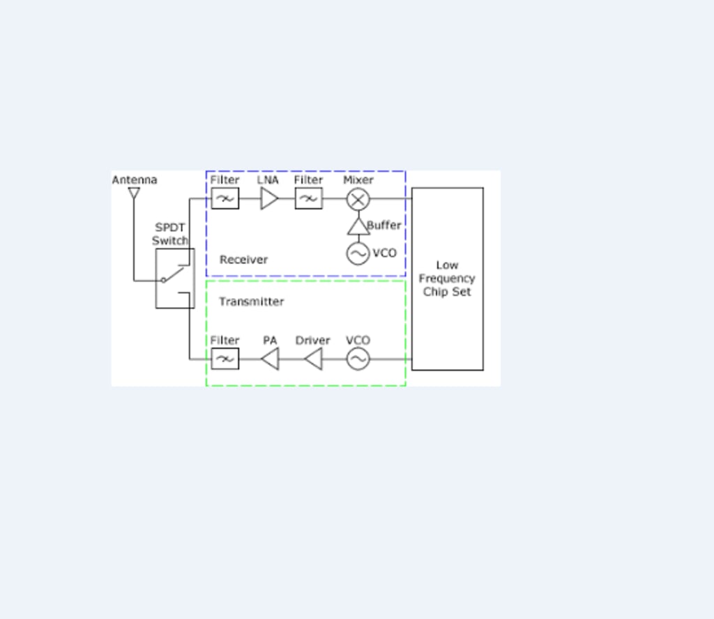
Introduction to RF & Wireless Communications Systems
RF & Wireless Communication

1. Marconi and the First Wireless Transmissions :
Radio Frequency (RF) and wireless have been around for over a century with Alexander Popov and Sir Oliver Lodge laying the groundwork for Guglielmo Marconi’s wireless radio developments in the early 20th century. In December 1901, Marconi performed his most prominent experiment, where he successfully transmitted Morse code from Cornwall, England, to St John’s, Canada.
2. What is RF?
RF itself has become synonymous with wireless and high-frequency signals, describing anything from AM radio between 535 kHz and 1605 kHz to computer local area networks (LAN's) at 2.4 GHz. However, RF has traditionally defined frequencies from a few kHz to roughly 1 GHz. If one considers microwave frequencies as RF, this range extends to 300 GHz. The following two tables outline the various nomenclatures for the frequency bands. The third table outlines some of the applications at each of the various frequency bands.
3.Relationship between frequency (f) and wavelength (λ):
relationship between frequency (f) and wavelength (λ). A wave or sinusoidal can be completely described by either its frequency or its wavelength. They are inversely proportional to each other and related to the speed of light through a particular medium.
RF measurement methodology can generally be divided into three major categories:
Spectral analysis, vector analysis, and network analysis. Spectrum analyzers, which provide basic measurement capabilities, are the most popular type of RF instrument in many general-purpose applications. Specifically, using a spectrum analyzer you can view power-vs-frequency information, and can sometimes demodulate analog formats, such as amplitude modulation (AM), frequency modulation (FM), and phase modulation (PM).
Vector instruments include vector or real-time signal analyzers and generators. These instruments analyze and generate broadband wave forms, and capture time, frequency, phase, and power information from signals of interest. These instruments are much more powerful than spectrum analyzers and offer excellent modulation control and signal analysis.
Network analyzers, on the other hand, are typically used for making S-parameter measurements and other characterization measurements on RF or high-frequency components. Network analyzers are instruments that correlate both the generation and analysis on multiple channels but at a much higher price than spectrum analyzers and vector signal generators/analyzers.
4. Why Operate at Higher Frequencies?
From Table 3 we notice that the frequency spectrum is quite fragmented and dense. This encompasses one of the reasons that we are constantly pushing applications into higher and higher frequencies. However, some of the other reasons accounting for this push into higher frequencies include efficiency in propagation, immunity to some forms of noise and impairments as well as the size of the antenna required. The antenna size is typically related to the wavelength of the signal and in practice is usually ¼ wavelength.
This leads to a very interesting question. Typically, data is structured and easily represented at low frequencies; how can we represent it or physically translate it to these higher RF frequencies? For example, the human audible range is from 20 Hz to 20 kHz. According to the Nyquist theorem, we can completely represent the human audible range by sampling at 40 kHz or, more precisely, at 44.1 kHz (this is where stereo audio is sampled). Cell phones, however, operate at around 850 MHz. How does this happen?
5. Frequency Shifting through Frequency Mixing :
Much of the study of RF and high-frequency measurements occurs in the frequency domain. There is a duality between the time-domain functions and those same functions represented in the frequency-domain. Figure 1 depicts frequency shifting the human audible range to transmit through cellular frequencies. The most common way to frequency shift is called mixing, which is equivalent to multiplying your signal by a sinusoidal signal. The following mathematical trigonometric identity demonstrates this fact.
6. Looking for more RF Basics?
Engineers who are new to RF or looking for a a refresher course can attend a 3-Day National Instruments RF Fundamentals Training Course to explore traditional measurements, learn about digital and analog modulation, examine modern system-level tests such as BER, MER, and EVM, and more.
7. Relevant NI Products :
Customers interested in this topic were also interested in the following NI products:
- RF Academy
- NI RF & Communications Platform
- NI 5663 6.6 GHz RF Vector Signal Analyzer
- NI 5673 6.6 GHz RF Vector Signal Generator
- NI 5671 2.7 GHz RF Vector Signal Generator
- NI RF Switch Hardware
8. Conclusions :
This document is meant to provide a brief overview and introduction to RF, wireless, and high-frequency signals. Additional information can be found in Teaching and Research Resources for RF and Communications.
About the Creator
Iftikhar Ahmed
Freelance writer.


Comments
There are no comments for this story
Be the first to respond and start the conversation.