
Fibers and Integrated Optics: Detectors and Receivers
A report presentation for Computer Engineering Graduate School - 616 Fiber and Integrated Optics. Index Terms - Detectors, Photodiode, Receivers, IEE 802.3 Ethernet


Learning Outcomes
- Explain the basic concept and operation of a PN photodiode when used in an electrical circuit.
- Explain the use of PIN photodiodes and the theory of operation.
- Describe the action of an avalanche photodiode (APD).
- Compare the factors in photodiode performance characteristics, including Responsivity, Quantum efficiency, and Switching speed.
- Discuss how fiber optic receivers are typically packaged with the transmitter and how together, the receiver and transmitter form a transceiver.
- Examine a block diagram of a typical receiver that is divided into three subassemblies: Electrical subassembly, Optical sub-assembly, and Receptacle.
- Describe the two key characteristics of a fiber optic receiver: Dynamic Range and Wavelength.
- Describe the performance characteristics of a fiber optic receiver to include: Recommended operating conditions, Electrical characteristics, Optical characteristics, and IEEE 802.3 Ethernet applications.
Index Terms - Detectors, Photodiode, Receivers, IEE 802.3 Ethernet
I. Photodiodes and Transceivers
PIN photodiode basics
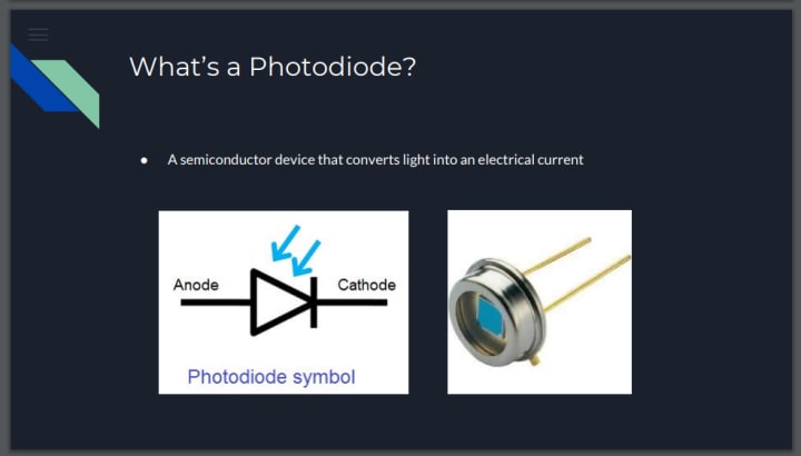
One of the key requirements for any photodetector is a sufficiently large area in which the light photons can be collected and converted. This is achieved by creating a large depletion region - the region where the light conversion takes place - by adding an intrinsic area into the PN junction to create a PIN junction.
One of the key parameters within the design of the PIN photodiode is to enable the light to enter the intrinsic region. The physical design of the photodiode needs to take account of this so that the light collection is optimized.
Photodiodes in general, and in this case, the PIN photodiode, will respond differently to different light wavelengths. It is generally the thickness of the top p-type region or layer that is one of the key parameters in determining the response sensitivity.
PIN photodiode applications
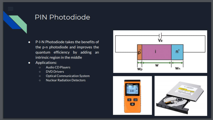
The PIN photo-diode does not have any gain, and for some applications, this may be a disadvantage. Despite this it is still the most widely used form of diode, finding applications in audio CD players, DVD players as well as computer CD drives. In addition to this, they are used in optical communication systems.
The PIN photodiode is also used as a nuclear radiation detector. There are several types of nuclear radiation. The radiation may be in the form of high energy charged or uncharged particles, or it may also be electromagnetic radiation. The diode can detect all these forms of radiation. The electromagnetic radiation, of which light is a form, generates the hole-electron pairs as already mentioned. The particles have exactly the same effect. However, as only a small amount of energy is required to generate a hole-electron pair a single high-energy particle may generate several hole-electron pairs.
PN photodiode

While the PIN photodiode is the most widely used, the PN photodiode is also used in some circumstances. It is essentially the same as the PN photodiode, except that it does not have an intrinsic layer within the depletion region.
PN / PIN photodiode comparison
Both PN photodiodes and PIN photodiodes are available on the market. When designing a circuit, it is necessary to choose the correct type. Both PN photodiodes and PIN photodiodes have their advantages and disadvantages:
- A PIN photodiode needs reverse bias for its operation as a result of the presence of the intrinsic region. This reverse bias has several consequences:
- Reverse bias introduces a noise current which reduces the signal to noise ratio.
- Reverse bias offers better performance for high bandwidth applications.
- Reverse bias offers better performance for high dynamic range applications.
- A PN photodiode does not require a reverse bias, and as a result, is more suitable for low light applications.
Avalanche Photodiode (APD)
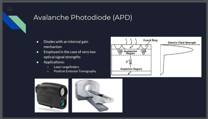
Avalanche photodiodes are diodes with an internal gain mechanism. As in the case of standard diodes, photons generate electron-hole pairs, which are accelerated by the applied external voltage such that further electrons are introduced to the conduction band through impact ionization. These secondary electrons can in turn absorb sufficient energy to raise further electrons into the conduction band. A multiplication factor of several hundred can thus be achieved.
Avalanche diodes are usually employed in the case of very low optical signal strengths, but are also used for applications with high modulation frequencies. As of frequencies of approx. 60 MHz, the noise level heightened by the avalanche effect is generally lower than that produced by a conventional diode in combination with external electronic amplification.
Typical applications include distance measurement at low signal levels and optical communication. First Sensor offers a wide range of APD detectors with different housings. With components optimized for the blue, red, and infrared spectral range between 905 and 1064 nm, our range includes the right solution for virtually all applications.
Responsivity
Responsivity measures the input–output gain of a detector system. In the specific case of a photodetector, responsivity measures the electrical output per optical input.
The responsivity of a photodetector is usually expressed in units of either amperes or volts per watt of incident radiant power. For a system that responds linearly to its input, there is a unique responsivity. For nonlinear systems, the responsivity is the local slope. Many common photodetectors respond linearly as a function of the incident power.
Responsivity is a function of the wavelength of the incident radiation and of the sensor properties, such as the bandgap of the material of which the photodetector is made.
Quantum Efficiency
The term quantum efficiency (QE) may apply to incident photon to converted electron (IPCE) ratio, of a photosensitive device or it may refer to the TMR effect of a Magnetic Tunnel Junction.
This article deals with the term as a measurement of a device's electrical sensitivity to light. In a charge-coupled device (CCD) it is the percentage of photons hitting the device's photoreactive surface that produce charge carriers. It is measured in electrons per photon or amps per watt. Since the energy of a photon is inversely proportional to its wavelength, QE is often measured over a range of different
wavelengths to characterize a device's efficiency at each photon energy level. The QE for photons with energy below the band gap is zero. Photographic film typically has a QE of much less than 10%, while CCDs can have a QE of well over 90% at some wavelengths.
Switching Speed
Switching speed (toggling speed) A measure of the rate at which a given electronic logic device is capable of changing the logic state of its output in response to changes at its input. It is a function of the delay encountered within the device, which in turn is a function of the device technology.
Transceiver
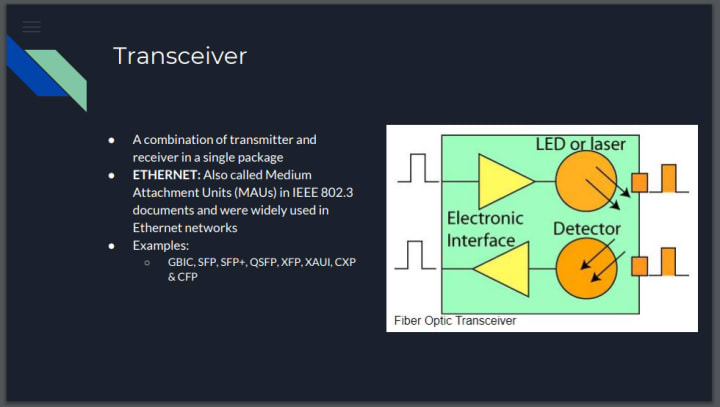
A transceiver is a combination transmitter/receiver in a single package. The term applies to wireless communications devices such as cellular telephones, cordless telephone sets, handheld two-way radios, and mobile two-way radios. Occasionally the term is used in transmitter/receiver devices in cable or optical fiber systems.
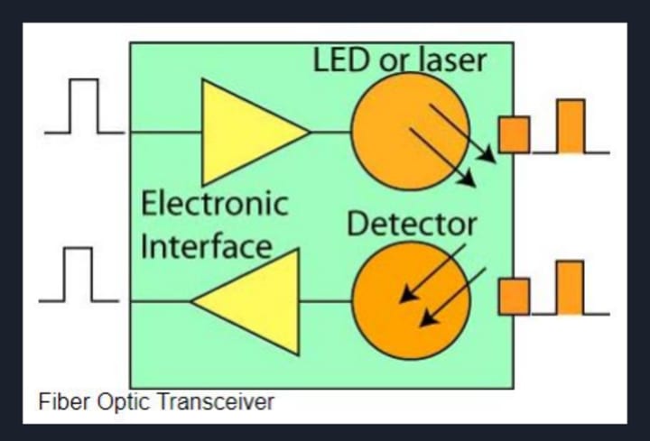
Most systems use a "transceiver" which includes both transmission and receiver in a single module. The transmitter takes an electrical input and converts it to an optical output from a laser diode or LED. The light from the transmitter is coupled into the fiber with a connector and is transmitted through the fiber optic cable plant. The light from the end of the fiber is coupled to a receiver where a detector converts the light into an electrical signal which is then conditioned properly for use by the receiving equipment.
Receivers use semiconductor detectors (photodiodes or photodetectors) to convert optical signals to electrical signals. Silicon photodiodes are used for short wavelength links (650 for POF and 850 for glass MM fiber). Long wavelength systems usually use InGaAs (indium gallium arsenide) detectors as they have lower noise than germanium which allows for more sensitive receivers.
II. Typical Receiver: Electrical Subassembly, Optical Subassembly and Receptacle
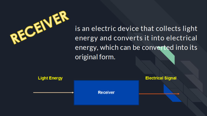
Many different fiber-optic receiver designs are in use today. The complexity of these receivers varies by application. The job of the receiver is to take the light energy from the optical fiber and convert it into electrical energy.
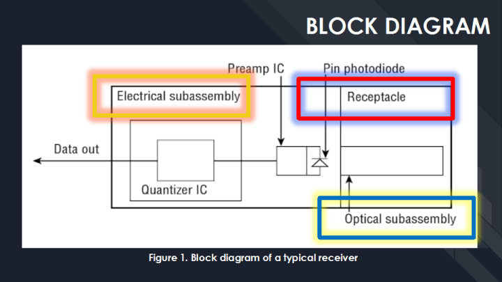
The output of the receiver is designed to interface with electronics that handle the information after the light-to-light conversion. A typical receiver can be broken into three subassemblies: receptacle, optical subassembly, and electrical subassembly, as shown in the Figure 1.
Receptacle
Regardless of the receiver packaging, the receptacle is the part of the fiber-optic receiver that accepts the connector. Its job is to provide alignment for the ferrule or terminus so that the optical fiber is perpendicular to the photodiode in the optical subassembly.
A ferrule (from Latin viriola, meaning little bracelet) is a ring or cap attached to an object to protect against damage, splitting, or wear. In fiber optic, a ferrule is a component (usually a rigid tube) used to align and protect the stripped end of a fiber.
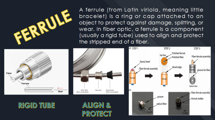
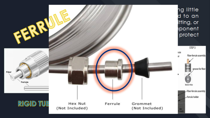
The ferrule is a rigid tube used to confine and support the stripped end of a fiber as found in connectors. The ferrule, usually made of metal or ceramic, is the central part of the male connector. It is designed to both align and protect the fiber Core during connection. The ferrule tip is polished to ensure a smooth finish on the fiber end. Polish can also minimize Connector Loss or back reflection, depending on the angle used. There are four types of polish: PC, super PC (SPC), ultra PC (UPC) and angled PC (APC).
Optical Subassembly
The Optical subassembly guides the light energy from the optical fiber to the photodiode. Depending on the receiver packaging, a window or terminus end face in the optical subassembly makes contact with the optical fiber end face. The window may be shaped a lens to focus the light energy onto the photodiode, as shown in the Figure 2, or a lens may be placed between the window and the photodiode.
In many receivers, the photodiode and pre-amplifier are housed in the optical subassembly. Sometimes the optical subassembly is referred to as the photodiode preamplifier subassembly. Note that photodiode used in a receiver does not produce a substantial electrical signal. Mounting the preamplifier as physically close as possible to the photodiode allows the preamplifier to receive the strongest electrical signal.

Electrical Subassembly
Electrical Subassembly is a typically built on a multilayer printed circuit board. This printed circuit contains the quantizer IC and other passive components required to complete the electrical circuit. The photodiode and preamplifier contained in the optical subassembly are electrically connected to the printed circuit board. A metal shield, shown in the Figure 3, is typically placed over the electrical subassembly. The shield serves two purposes; it protects the electrical subassembly from external electromagnetic radiation, and it reduces the amount of electromagnetic radiation from the electrical subassembly.

A. Characteristics of Fiber Optic Receiver
This section examines fiber-optic receiver dynamic range and operating wavelength. The data used in this section was extracted from manufacturer datasheets and represents typical performance characteristics of readily available laser or LED fiber optic receivers.
1. Dynamic Range
Fiber-optic receivers are limited in the amount of optical input power they can receive. Too much optical input power will saturate the photodiode. Saturating the photodiode prevents the photodiode from turning off after the light pulse has been absorbed. This can cause electrical output pulses of the receiver to overlap, creating a bit error.
The dynamic range of the receiver is measured in decibels. It is the difference between the maximum and minimum optical input power that the receiver can accept. If the maximum optical input power is –14dBm and the minimum optical input power is –32dBm, the dynamic range would be the difference between the two values, or 18dB.
The receiver will generate a minimum number of errors when the optical input power is kept within the minimum and maximum values. All receivers generate errors. Error generation is typically described by the receiver’s bit error rate (BER). A typical receiver may have a BER of one error in a billion to one error in a trillion. Typically, this would be written as 10-9 or 10–12, respectively.
Example:
A typical 1300nm receiver may have an operating wavelength range from 1270nm to 1380nm.
2. Operating Wavelength
Fiber-optic receivers are designed to operate within a range of wavelengths. A typical 1300nm receiver may have an operating wavelength range from 1270nm to 1380nm. This is because fiber optic transmitters output optical energy within a wavelength range. The receiver must be able to accept a 1300nm transmitter that has a center wavelength of 1275nm or 1375nm. A receiver designed for 1300nm may not perform well or may not perform at all when connected to an 850nm or 1550nm transmitter because the responsivity of the photodiode changes over a range of wavelengths.
Exercises
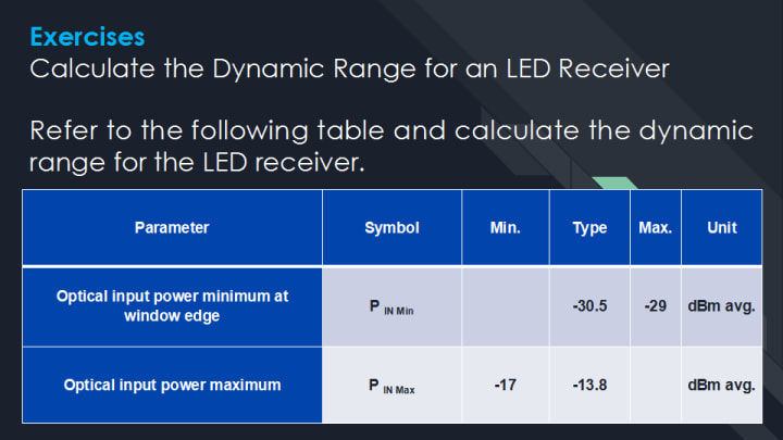
Calculate the Dynamic Range for an LED Receiver
The dynamic range of the LED receiver is the difference between the minimum value for the maximum optical input power and the maximum value for the minimum optical input.
Refer to the following table and calculate the dynamic range for the LED receiver.
Solution:
To calculate the dynamic range, subtract the minimum value for the maximum optical input power (P IN Max) from the maximum value for the minimum optical input power (P IN Min) as shown in this formula:
P IN Max – P IN Min = Dynamic Range
–17dBm – –29dBm = 12dB
Dynamic range = 12dB (Answer)
Exercises
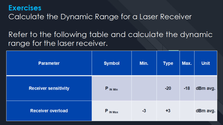
Calculate the Dynamic Range for a Laser Receiver
The dynamic range of the laser receiver is the difference between the minimum value for the maximum optical input power and the maximum value for the minimum optical input.
Refer to the following table and calculate the dynamic range for the laser receiver.
Solution:
To calculate the dynamic range, subtract the minimum value for the maximum optical input power (P IN Max) from the maximum value for the minimum optical input power (P IN Min) as shown in this formula:
P IN Max – P IN Min = dynamic range
–3dBm – –18dBm = 15dB
Dynamic range = 15dB (Answer)
B. Performance Characteristics of a Fiber Optic Receiver
The performance characteristics of the LED receiver are typically broken up into four groups:
- Recommended operating conditions
- Electrical characteristics
- Optical characteristics
- Data rate
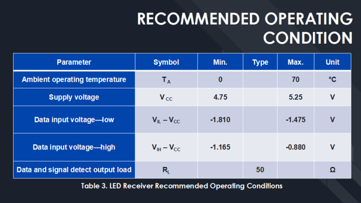
Recommended Operating Conditions
The recommended operating conditions describe the maximum and minimum temperature and voltage ranges that the device can operate in without damage. Table 3 shows the typical recommended operating conditions for a 1300nm 100Mbps LED receiver.
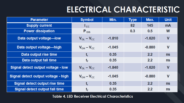
Electrical Characteristics
The electrical characteristics of the LED receiver describe the supply current requirements, data output voltages, signal detect output voltages, rise/fall times, and power dissipated by the device. Table 4 shows the typical electrical characteristics for a 1300nm 100Mbps LED receiver.
Optical Characteristics
The optical characteristics of the LED receiver at a minimum include minimum optical input power, maximum optical input power, and operating wavelength. Table 5 shows the typical optical characteristics for a 1300nm 100Mbps LED receiver.

If the LED receiver optical characteristics are known, the dynamic range for the receiver can be calculated. The dynamic range is the difference between the minimum value for the maximum optical input power and the maximum value for the minimum optical input. The minimum value for the maximum optical input power in Table 5 is –14dBm. The maximum value for the minimum optical input power is –31dBm. (Remember that this information should be obtained from the manufacturer’s data sheet.)
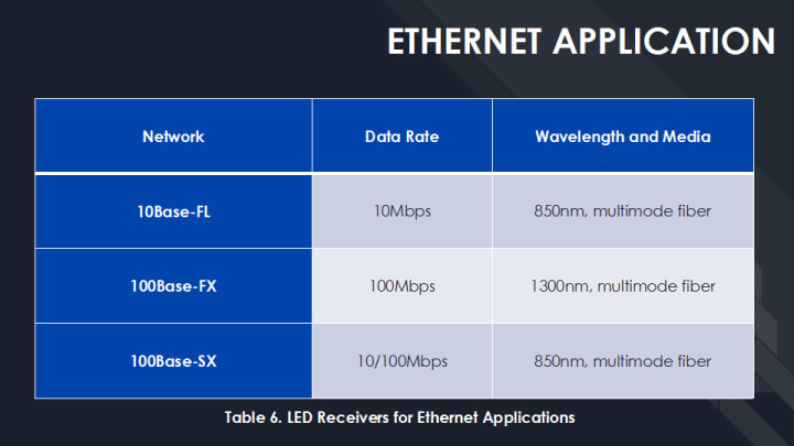
Ethernet Application
LED receivers are typically designed to support one or more network standards. A 100Mbps 1300nm receiver could support a 100Base-FX Ethernet application or a 100Mbps ATM application. Table 6 lists the data rates, wavelengths, and optical fiber type for various LED receivers used in IEEE 802.3 Ethernet communication systems.
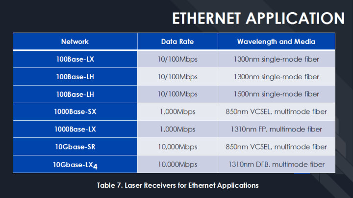
Laser receiver can typically support multiple data rate operations. The same receiver may be used with data rates ranging from 155Mbps in an ATM switch to 2.5Gbps for a SONET OC-48 switch. Table 7 lists the data rates, wavelengths, and optical fiber type for various laser receivers used in IEEE 802.3 Ethernet communication systems.
Supplemental Information
On march 28, 2017 at Piscataway, New Jersey, in the News and Events on the Press Releases from IEEE Standards Association, IEEE Announces Industry Connections Activity: New Ethernet Applications

III. Conclusion
This report presentation covered photodiode fundamentals and the basic optical, electrical, and mechanical components found in a typical fiber-optic receiver. We examined the basic optical performance characteristics of the receiver and learned when an optical attenuator is required.
IV. References
- Alwayn, V. (2004, April 23). Fiber-Optic Technologies. http://www.ciscopress.com/articles/printerfriendly/170740
- Electronics Notes. (2019, February 04). PN Photodiode and PIN Photo Diode. https://www.electronics-notes.com/articles/electronic_components/diode/photodiode-detector-pn-pin.php
- Electronics Notes. (2019, February 04). What is Ethernet IEEE 802.3. https://www.electronics-notes.com/articles/connectivity/ethernet-ieee-802-3/basics-tutorial.php
- Electronics Projects Focus. (2019, February 04). What are the Basic Elements of a Fiber Optic Communication System?https://www.elprocus.com/basic-elements-of-fiber-optic-communication-system-and-its-working/
- First Sensor. (2019, February 04). Avalanche photodiodes (APD). https://www.first-sensor.com/en/products/optical-sensors/detectors/avalanche-photodiodes-apd/
- Institute of Electrical and Electronics Engineers. (2017, March 28). IEEE Announces Industry Connections Activity: New Ethernet Applications. https://standards.ieee.org/news/2017/ieee-802-3.html
- Oliviero, A., & Woodward, B. (1966). Cabling : the complete guide to copper and fiber-optic networking / Andrew Oliviero, Bill Woodward. — 4th ed. p. cm. ISBN 978-0-470-47707-6
- Photonics Media. (2019, February 04). Fiber Optics: Understanding the Basics. (https://www.photonics.com/Articles/Fiber_Optics_Understanding_the_Basics/a25151
- TechTarget Network. (2019, February 04). Transceiver. https://searchnetworking.techtarget.com/definition/transceiver
- The Fiber Optics Association, Inc. (2019, February 04). Guide to fiber optics and premises cabling. http://www.thefoa.org/tech/ref/appln/transceiver.html
- Woodward, B., & Husson E. B. (2005). Fiber Optics Installer and Technician Guide, Bill Woodward, Emile B. Husson — 1st ed. ISBN 978-0-7821-4390-4
- Woodward, B., & Oliviero, A. (2015). Fiber Optics Installer (FOI) Certification Exam Guide, ISBN: 978-1-119-01150-7.
About the Creator
Domingo Añasco-Gaces Samontina, Jr.
.Professional Member of the Mechatronics and Robotics Society of the Philippines
.Certified Documented Information Controller with TUV Rheinland Qualifications
.Master of Science in Engineering (on-going) with Professional Teacher Certificate
Keep reading
More stories from Domingo Añasco-Gaces Samontina, Jr. and writers in 01 and other communities.
Diverting Bottles
Diverting Bottles is a technical process of transferring the bottles using a conveyor. In this case, a conveyor device was used to divert the bottles from one conveyor belt to another. This method is usually used in factories where the bottles need to be sorted depending on their physical features. Usually, a bottling conveyor is used to do the following tasks:
By Domingo Añasco-Gaces Samontina, Jr.4 years ago in 01
React Native for Cross-Platform App Development: Strategies & Services
Businesses are adopting all the emerging approaches to reach their target audience. They are seeking advanced and cost-effective digital solutions to establish their brand presence. Cross-platform development has steered up the new trend in the past few years. Many platforms and tools offer accessibility to build apps aligning with versatile needs. React Native is a popular tool that can deliver user-friendly apps rapidly.
By Erma Winter7 days ago in 01
A Day in the Life of a Neuro AI Researcher
Neuro AI research, the intersection of neuroscience and artificial intelligence, is a burgeoning field that holds immense promise for understanding the intricacies of the human brain and developing advanced AI systems. In this article, we'll delve into the daily routine of a NeuroAI researcher, exploring the challenges, rewards, and moments of inspiration that define their work.
By James Moodya day ago in 01


Comments
There are no comments for this story
Be the first to respond and start the conversation.